


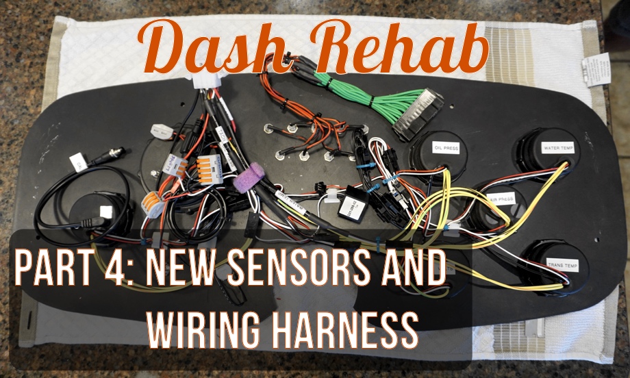
In Part 3 of our Dash Rehab series, we showed our solution to one of our trickiest sensors: the oil pressure gauge. Thankfully, none of the other sensors gave us that much trouble. We bought our new gauges from Speedhut.com, and all the gauges came with very detailed instructions as well as new sensors and wires to hook everything up. (Not a sponsored post. After researching gauges, we picked these out and paid retail price for them. We just really like them, so we want to share.)
New Sensors
More important than the way the gauges look is ensuring that they function correctly. Our bus has a very old engine that does not have the benefit of any modern electronic aids. This makes the gauges and sensors critical to ensuring that everything is running correctly. For our gauge selection we chose:
- Water Temperature
- Oil Pressure
- Air Pressure
- Transmission Temperature
- System Voltage
- Speedometer
- Tachometer
General Gauge Wiring
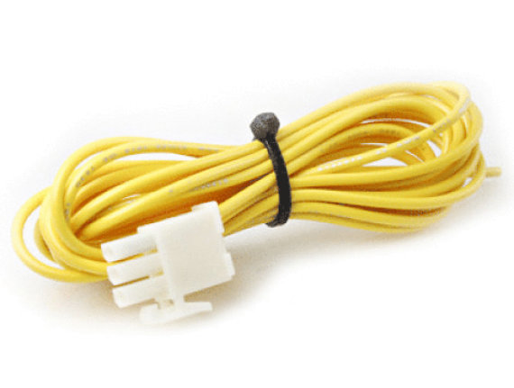
Each gauge in our cluster came with at least two sets of wires coming out of it: one set is for gauge power (+12V key, Ground, +12V lights), and the other set is for backlighting (+12V lights, Ground). Each also includes an input for the sensor wire, which is generally a 1-, 2-, or 3-wire connector. Also included with each gauge is an approximately six foot wire that has a watertight automotive-style connector on the sensor side and a clip connector on the gauge side.
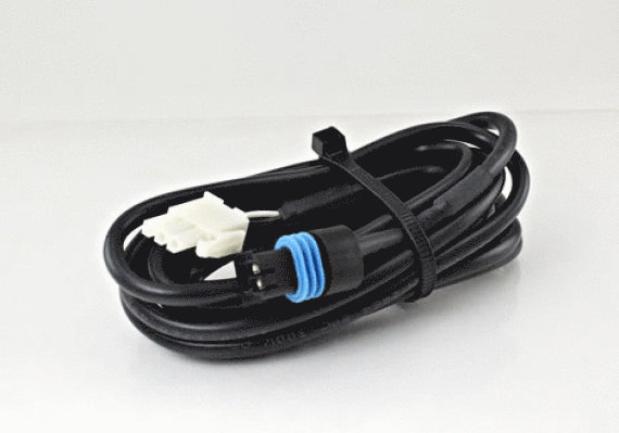
Because our engine is over 35ft away from our gauges, we chose to cut the included cable and solder it into the existing bus wiring. On the gauge-side, we decided to make a wiring harness for the new gauges (more on that at the end of the post).
Water Temperature
When we were first looking into buying an old bus, we were told that the old Detroit 2-stroke engines are VERY reliable as long as you ensure three things: 1: Do not "lug" them (running them at a low RPM in too high of a gear) 2: Do not let them run out of oil (and change it regularly) because they leak 3: NEVER let them overheat.
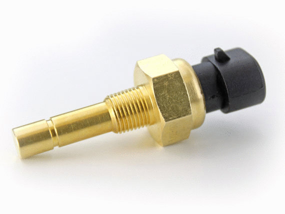
Our bus did originally come with a coolant temperature gauge, but something was very wrong with it. When we would turn the lights on, the indicated temperature would jump at least ten degrees - alarming, to say the least. The old sensor was a single wire unit that had a lead on top of the sensor. The new sensor was a 2-wire unit in a weatherproof boot with a ground and signal wire. It was easy enough to run a ground to the rear engine cover and solder in the signal wire to the existing wire.
To verify that the gauge was functioning correctly, we used a non-contact laser infrared temperature gun that we purchased when we were testing the RV refrigerator ($15 on Amazon). To our surprise, the gauge was reading within one degree of our little laser temperature gun!
Oil Pressure
The oil pressure sensor was the main subject of our last post (found here). The main issue was that the sensor we were replacing was a 1-wire sensor, and our new sensor is a 3-wire sensor. To verify this gauge is working correctly, we have a mechanical gauge in the engine bay that reads the pressure right at that point. That gauge and the new gauge display the exact same readings.
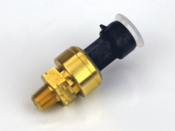
Air Pressure
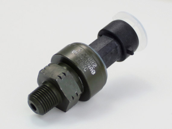
The original air pressure gauge that came with the bus was a mechanical gauge that needed a direct line to the air pressure lines. This was a clumsy solution that limited where the gauge could be installed and was prone to leaks and bad fit. Our new air pressure gauge came with a remote sensor that just has three wires coming from it. To be fair, the old gauge was working perfectly fine - showing an indicated working range of 90 psi to 120 psi anytime the bus was in operation. To verify this gauge is working correctly we just make sure it is still reading in that range when the bus is fully warmed up.
Transmission Temperature
Our bus came with two oil temperature gauges. Neither of these gauges worked, and one of them was not even hooked up to anything! The one that was hooked up never worked. I narrowed it down to the sending unit before I decided to get all new gauges,even going as far as ordering a new sending unit. Luckily our new transmission temperature gauge came with the correct sender (2-wire) and was easy to wire up. To verify, we again pulled out the non-contact laser infrared temperature gun - temperature readings were spot on.
System Voltage
Our bus runs a 12 Volt negative-ground system, similar to most modern cars. It relies heavily on a voltage regulator mounted in a bay behind the starter batteries to maintain this voltage. When the bus first starts up, the voltage regulator takes a few seconds to start working. This can be seen because the voltage will read 12.5 volts (standing battery voltage) and a warning light on the dash will be lit. After a few seconds the light turns off, and the voltage jumps to about 14.5 volts. To test this gauge, we simply use a voltage meter to verify the readings.
Speedometer
The speedometer that came with our bus was MOSTLY working. Anything above 20 mph seemed to work just fine, with the needle operating smoothly and odometer tracking miles as it should. The problem was that below 20 mph the needle would start to bounce. Initially, because of this behavior, I thought this must be a mechanical speedometer that had some friction in the cable. When I took the old speedometer apart, however, I discovered that it was actually electrical (two wires) and the signal was being generated from the front driver's side wheel.
Speedometers can be tricky because even the same tire size from two different manufacturers can vary enough to throw it off. Same with changing to a different tire profile or size. Many speedometers come with provisions for handling this by allowing you to set the "ratio" in the speedometer somehow.
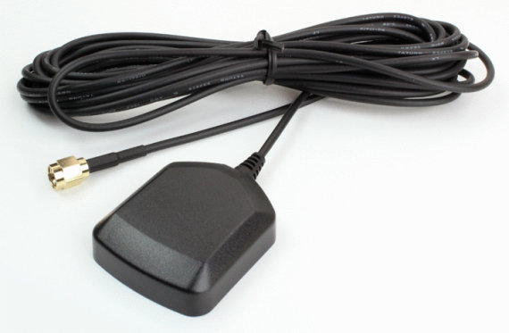
The speedometer we chose has an even more clever solution: They use GPS to measure the speed. I have to admit that I was skeptical at first - "what if you are in a tunnel" - "what if there is not a clear path to the satellites". However, after hours of researching online, I couldn't find a single reviewer with a bad thing to say about them or claim that they operated incorrectly. An added benefit is that we can get a clock, altitude, 0-60 times, and 1/4 mile times with the gauge (because we really need to know if we will beat the dragsters off the line). I have to admit that so far I am very impressed. The speedometer has functioned flawlessly.
Tachometer
The last gauge we decided to add was a tachometer to measure the engine speed. Our bus did not originally come with a tach, but we thought it would be a very useful addition. With Detroit Deisel 2-stroke engines, you have to maintain a relatively high RPM to get usable power out of them. We were also warned against "lugging" the engine - by running too low RPM while trying to climb a hill. Even though we have an automatic transmission, a tach is still very useful for engine braking (Jacob's braking).
We had read on different bus forums that you need a special magnetic sending unit to make a tach work well. We also ran across another post that said you could use the "RELAY" terminal on the factory generator to get a signal. The complication with this is that the generator is a 6-pole generator coupled with the fact that the generator is at a ratio of about 2.3:1 with the crankshaft, giving a final working ratio of about 13.7:1 - not an easy or exact thing for most tach gauges.
Fortunately, the tachometer we ordered allowed for very easy programming. This was crosschecked with an optical tachometer that was purchased for about $18 on Amazon (full details and blog post on this coming very soon).
Wiring Harness
Now that all the sensors were taken care of, it made sense to clean up the mess of wires behind the dash.
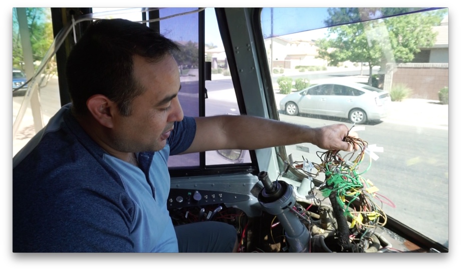
Before we took the old gauges out, we labeled everything and verified signals and voltages. Knowing that there would be a high probability of removing the dash multiple times, we decided it would be a smart idea to make a wiring harness to keep all the wires organized and tidy.
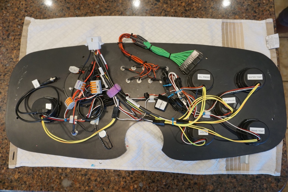 For no good particular reason, we decided to use an ATX cable extension to connect all the warning lights. We used a Molex style connector to wire in the gauges. I happened to buy a few of these when I was at Fry's Electronics buying wire and shrink tubing. I found the exact same connectors on Amazon for about $15. You need a special crimping tool to wire these up but we are very pleased with the results. Here is the link to the exact ratcheting crimping tool we had already purchased to build the battery with (for about $35). In retrospect, we liked the Molex connector better than the ATX connector we used on the lights. If we had to do it again, we would have just used Molex for both the gauges and the lights, but they are both working great right now.
Check out the video:
Click here If you cannot see the video.

0 Comments
Comments powered by Disqus