


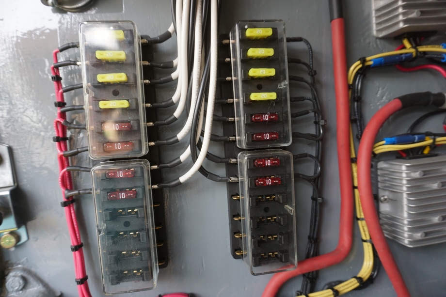
Last week, we put the converters, relays, and fuses on our board and got it wired into the supply side. We did some preliminary testing to ensure that everything was connected correctly.
This week, we finished wiring everything up. We ran the control wire for the "backup" system power, ran all the 12V circuits from the fuse box to their destinations, and wired in a generator plug.
Testing
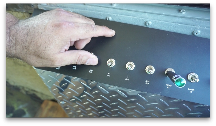
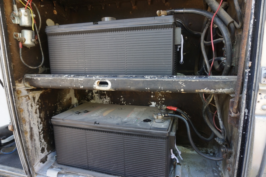
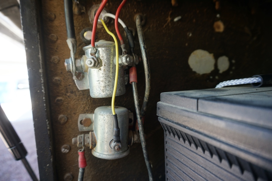
To test our "backup" power (our chassis starting batteries - 2 large 8-D batteries used to start and run the coach), we needed to wire up the switch we have inside the bus. Fortunately, when we were redoing the driver's switch panel, we prepared for this by wiring an "aux battery" switch to a solenoid that was installed by the previous owner for this very purpose.
 Now, all we needed to do was run a wire from that solenoid to our designated terminal post. We ran that wire using a 14 AWG white wire. We measured the current draw of all 12 relays and found it to be just over 2 Amps, so 14 AWG should do just fine. Once we wired that up, we turned off the breaker from the 48 Volt battery to the converters. This showed us 0V at the output of our fuse block. We then flipped the switch and heard all the relays click and saw that the Volt meter read 12.60 Volts. Success!
DC House Cable
For the main wire to feed our 12 Volt circuits, we chose to run Waytek 10/2 Marine grade cable. This wire has two conductors of 10 AWG stranded tinned cable. The wire is UL listed as well as rated for 30 Amps of continuous current.
Our circuits consist of four 20 Amp circuits and four 10 Amp circuits, so this cable should be more than adequate to carry that load. This will also give us a little headroom if we decide we need more power in the future.
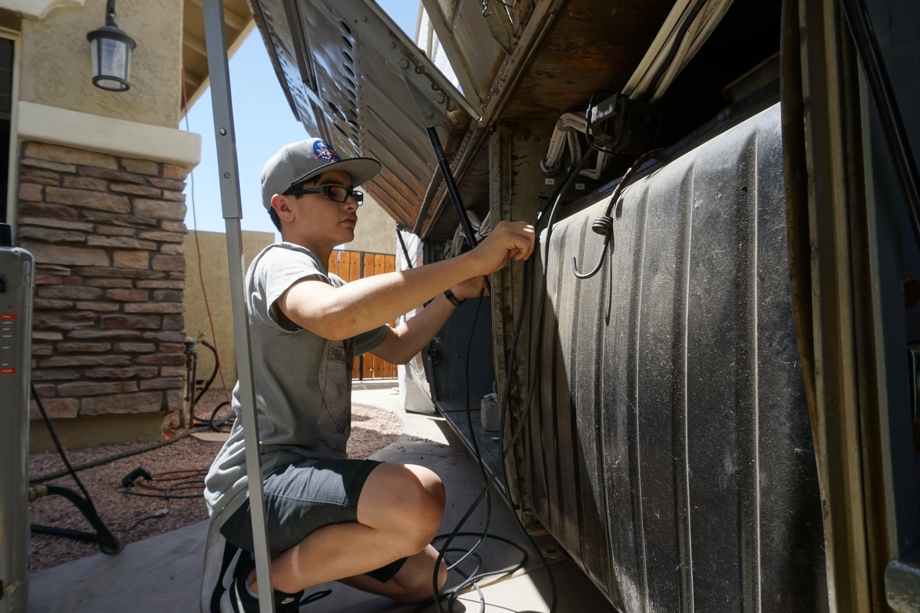
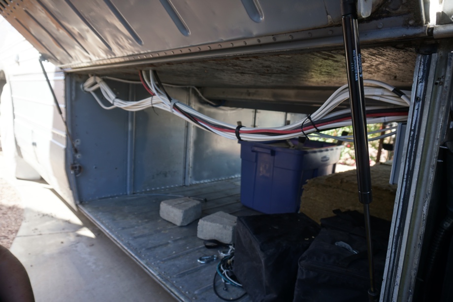
Running the Cable
Just like our 120V runs, we chose to run the cable on the ceiling of the bays in two raceways that run on either side of the bus. This wire looks nearly identical to the 120V wire, so we used labels everywhere to distinguish them. To further distinguish AC wires from DC wires we used lower-case letters for labeling on DC and upper-case for AC wires. We also took this time to run the wires for the solar (8 AWG black and red) as well as 2 network cables (for the Victron equipment), 1 VE.Direct cable (for the solar charge controller), and 1 DB-9 cable for the REC BMS display screen. We still have 1 set of cables to run to each bay that will power the 12 Volt bay lights (that we still have to decide on and purchase if you have any suggestions).
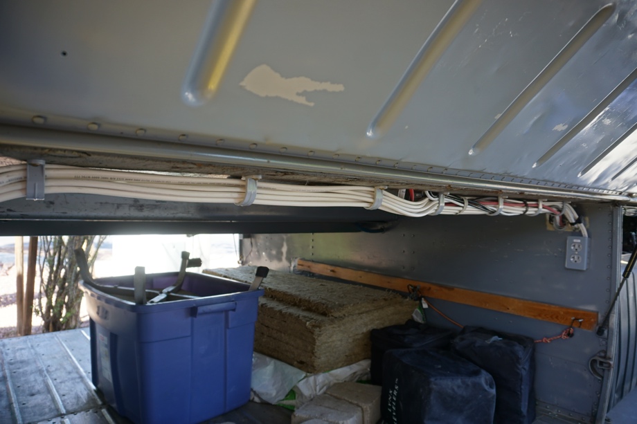
Securing the Cables
Even though we are not 100% done with running all the cables, it was close enough that we felt we needed to put some effort into starting to tidy things up a bit. The wire runs had gotten pretty large and wires were starting to hang all over the bays. The previous owner had run wires (although far fewer) in a similar way and used large plastic staples. These came loose over time and started sagging or had fallen out. We looked at a few alternatives including raceways that are used in networking to keep wires orderly. In the end, we decided to use some plastic conduit clamps and wrap the wire a non-adhesive vinyl wrap.
Generator Wiring
The last item we did this week was to connect the generator plug. With as much solar (3480 Watts) and battery capacity (24 kWh) that we have, we hope not to have to use a generator at all. Unfortunately, this is probably a bit too optimistic. We will likely purchase a small (3000-4000 Watt) generator as a backup.
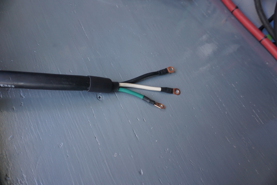
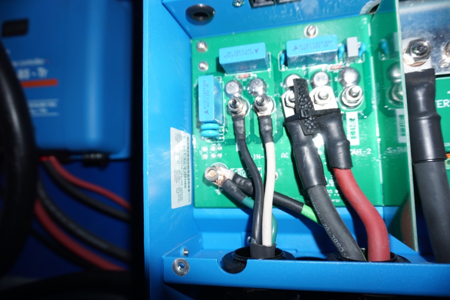
Doing a little research we discovered that most generators have a 30 Amp RV-plug (NEMA tt-30p). Thankfully, we held onto the old 30 Amp RV cable when we took apart the bus's previous electrical system, so we used it to wire into our "AC-IN 1" connector on our Victron Quattro inverter. For now, we kept the original 30-Amp RV plug (NEMA tt-30p) and just coiled up the wire in the A/C bay for the battery. If we need to run a generator, we will pull the cable out and run the generator outside but near the bus. If we find that we need to use a generator more frequently, then in the future we can run that cable to a more permanent location for a generator.
Wrapping Up The Outside Wiring
Other than those bay lights, we are now done with the outside wiring. It is quite a relief. We are looking forward to working on the inside of the bus. There are a few big projects that need to happen first though.
Coming up over the next couple of months: Polishing the aluminum, having the bus painted(!!!!!), and planning and finally installing solar panels. Once those solar panels are installed, we can finally get inside. We can't wait!
Watch the video:
Click here If you cannot see the video.
Parts We Used
Cantex Plastic Condiut Clamps in 1 1/4", 1", 3/4" and 1/2"
Velcro fastening cable ties
GRK 1 1/4 cabinet fasteners
Female spade connectors for 10 AWG wire
Heat Shrink tubing


Tools We Used
Small Crimpers
This drill is amazing


0 Comments
Comments powered by Disqus