


We are starting a four-part series on our major electrical components. In this series, we will share our research and thoughts as to why we selected REC BMS, the Victron Quattro inverter, the Victron Color Control GX, and the Victron Smart Solar MPPT solar charge controller. We will also go into detail about how we wired and set up each of these components. First up is the REC BMS.
We finally have everything in place to start testing things on our electrical system. The first order of business is to ensure the BMS (Battery Management System) is up and running. If you are not familiar with the function of a BMS, please see the very end of our post on wiring the BMS. It provides a brief introduction into what a BMS is and what it does. The post you are reading now will focus specifically on the BMS we chose for our build: The REC 1Q-16S with Victron CCGX support.
Why is a BMS Important?
A BMS is important because batteries, especially lithium batteries, can be dangerous if not monitored. Everybody has heard about cell phones and laptop computers with lithium batteries catching fire or overheating. The risk for this type of event is increased many times over when the battery is overcharged or allowed to discharge further than it was designed to do. When we first decided to experiment with these batteries, a BMS was the first thing we considered a "must have". We rank it right up there with carbon monoxide and smoke detectors.
Why Did We Choose REC?
As we shared in this previous post, we found two really great solutions for our battery. The first one was from Orion BMS and it seemed like a really solid product. The other was from REC. I think either of these two would have really been great for us. I wrote each of them an email explaining our situation - what type of battery we are using, what inverters we are using, MPPT solar charge controllers etc. They were both very prompt and helpful with their responses, but the REC-BMS guys seemed more "in tune" with what we were doing. Their answers were much more specific and they just really went out of their way to fully answer my questions. The Orion guys really felt more like they were targeting the EV car market, and the REC BMS guys were more in the "off grid" and "boat" camp.
Functions & Benefits of the REC BMS
 * Monitors our battery so that each cell's Voltage stays within set parameters. The parameters are tunable via software, but for the chemistry of our Nissan Leaf battery (LiMn2O4 with LiNiO2) the absolute max and absolute min are 4.2 Volts and 3.0 Volts respectively with a nominal voltage of 3.8 Volts. We will be tuning our parameters much lower with a max of 4.10 volts and a min of 3.35 volts. If the battery goes out of the parameters, the BMS will shut the battery off and sound an alarm. We want to tune them lower because we can get much, much more life (up to 5X) if we don't charge them to the absolute maximum and don't deplete them to the absolute minimum.
Monitors the health of the battery by taking internal DC resistance measurements.
Monitors the temperature of the batteries. The BMS has 3 temperature probes in the batteries to gather this information. It will shut the system down if the batteries get too hot and not allow charging if the temperature is below 0⁰ C. (Lithium batteries cannot be charged if the temperature is below freezing)
Monitors its own internal temperature.
Balances the cells. The BMS will measure each cell as it is charging. Cells that are at a higher Voltage than other cells will be balanced by discharging across a resistor. This is also tunable via software.
BMS current measurement using a precision shunt resistor. This allows us to get a very accurate "State of Charge" number allowing us to see what % we have left in the battery.
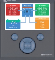
Interfaces natively with the Victron Color Control GX using the proprietary Victron VE.Can protocol.
Displays information at the cell level in real time on its own dedicated touch screen.
Precharge circuit. Prolongs the life of our equipment by sending a trickle charge to components so that they don't get hit with the "in-rush" of current. See: Wikipedia Article
Contactor. Works as the primary on/off switch the BMS uses if it detects a problem.
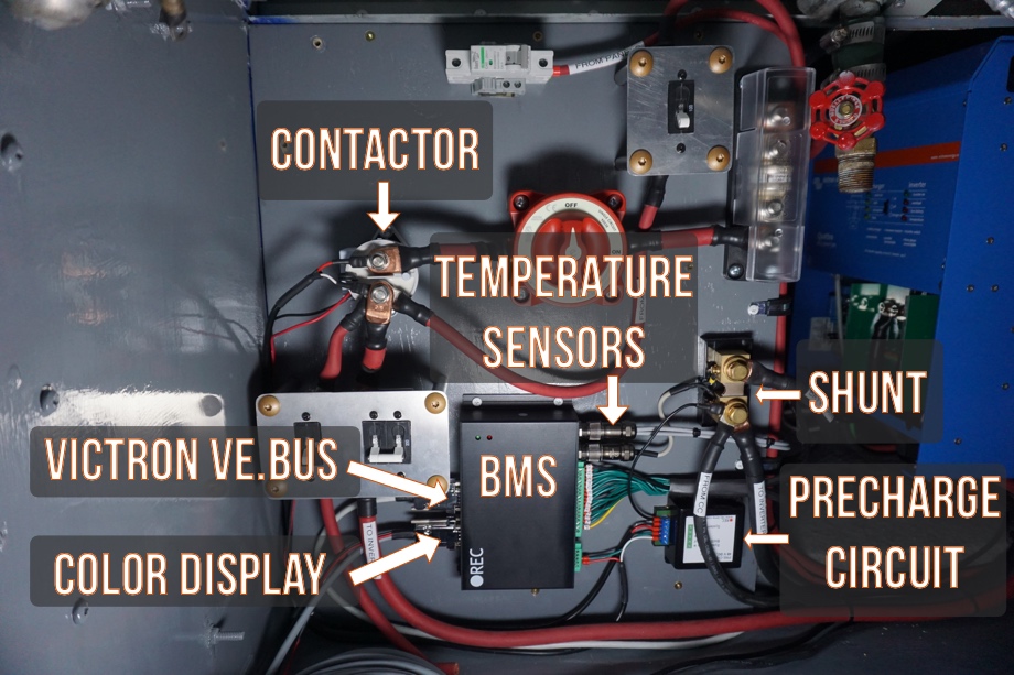
Wiring the BMS
Cells
We used 18 AWG wire to connect to each "cell" of the battery to the "BMS Unit cell Connector". Keep in mind that in our configuration of the Nissan Leaf modules, one "cell" is actually 14 smaller 33 Ah pouches wired together in parallel.
- Please see our post on reconfiguring the battery for battery config details. (14s14p configuration)
- Please see this post for the physical details of how the BMS was wired.
- Please see this diagram for a high-resolution diagram of how the cells are wired (thank you Krzys!)
Temperature Probes
The temperature probes have a dedicated harness and plugin terminal. The Nissan Leaf modules have a great little space between the pouches to insert these probes. Please see this video to see where we installed the probes.
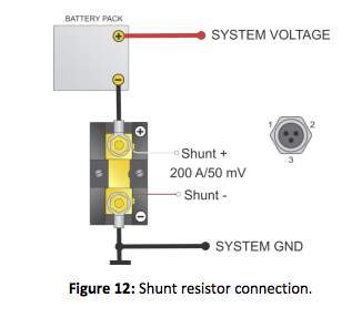
Shunt
The shunt has a similarly dedicated harness to the temperature probes. Once we decided where the shunt was going to be mounted we cut the wire and installed new ring connectors to keep the shielded cable as short as possible.
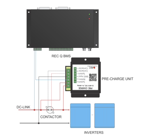
Pre-Charge Circuit
For the pre-charge circuit, we used a few wires we had laying around from the install of the new gauges and some very small ferrules. The manual comes with detailed instructions on how to wire this:
Victron VE.Can Interface
REC provided a DB9 to Ethernet cable designed and tested specifically to work with the BMS and the Color Control GX interface. This was as simple as plugging in the cord.
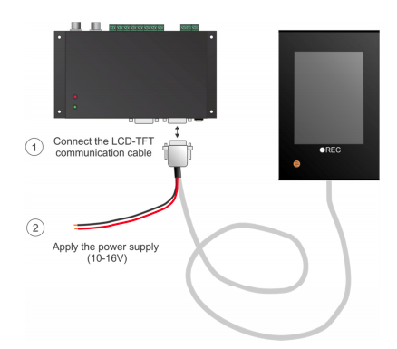
Real-time Color Display
The REC real-time color display module comes with the DB9 cable to plug into the BMS unit. We also have to connect 12 Volt power.
Setup
After wiring up all of the components, we were ready to fire it up. The first thing we did was test Voltages with the multimeter to make sure each cell was where we expected. At long last, we connected the battery's main positive and negative cables, turned on the main power switch, and turned on the BMS. We were then able to connect the BMS to the laptop and start setting all of the necessary parameters. Everything went smoothly and seems to be working perfectly.
Cost
We bought almost everything REC BMS offered. We thought that this would ensure that the system was tested and that all the components would work together seamlessly. Their prices were also very reasonable.
| Item | Cost |
|---|---|
| REC SI BMS Unit | €315.00 |
| Current Sensing Shunt (200A) | €45.00 |
| 2 Addtional Temperature Sensors | €12.60 |
| Precharge resistor (delay @ 48V) | €25.10 |
| PC Sofware BMS Master Control + cable | €55.00 |
| LCD touch display for REC BMS | €130.00 |
| Fuse (200A) | €15.40 |
| Fuseholder | €26.80 |
| Cable CAN (DB9 to RJ45) 2m | €6.40 |
| Power Relay Tyco EV200ADANA (48V) | €135.00 |
| Parcel costs | €45.83 | Total | €812.13 |
Exchange rate at the time: 1 USD = 0.81 EUR
€812.13 EUR = $1,003.44 USD
Final Thoughts
We are happy with how the wiring, install, and setup of the REC BMS has gone so far. One more bonus, REC has wonderful customer service. They have answered all of our questions with enthusiasm and are extremely helpful. Their company is located all the way around the world in Slovenia, and yet they always reply to our emails within a few hours. As we get the rest of the system up and running and have actually used the system for awhile, we will report back on how the BMS is doing. For now, we are really excited to have this part done. Next up in electrical setup: final setup and programming of the Victron inverter.
Watch the video below for more details on the software, how we set everything up, and how all of the different components work.
Click here If you cannot see the video.

0 Comments
Comments powered by Disqus