


After reconfiguring the Leaf battery modules into a 48V system, we were ready to build a stand for them. It needs to fulfill a few requirements. First, it needs to support the upper portion of our battery bank which weighs in at about 200 pounds (400 pounds for both upper and lower banks). Second, it needs to hold the entire battery securely in the bus as we travel down freeways or bumpy roads. Third, it needs to provide a way to physically bolt the entire thing to both the floor of the bus and the wall of the bay it is in.
Juan had a whole plan in his head, but it still required quite a bit of measuring, planning, test fitting (which is quite a pain with these huge beasts of battery banks), revising, etc. In the end, though, the plan that Juan had in his head was able to be sketched out with precise measurements and finally executed.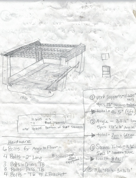
The first thing we did was cut two pieces of angle iron to fit the length of the lower battery bank. 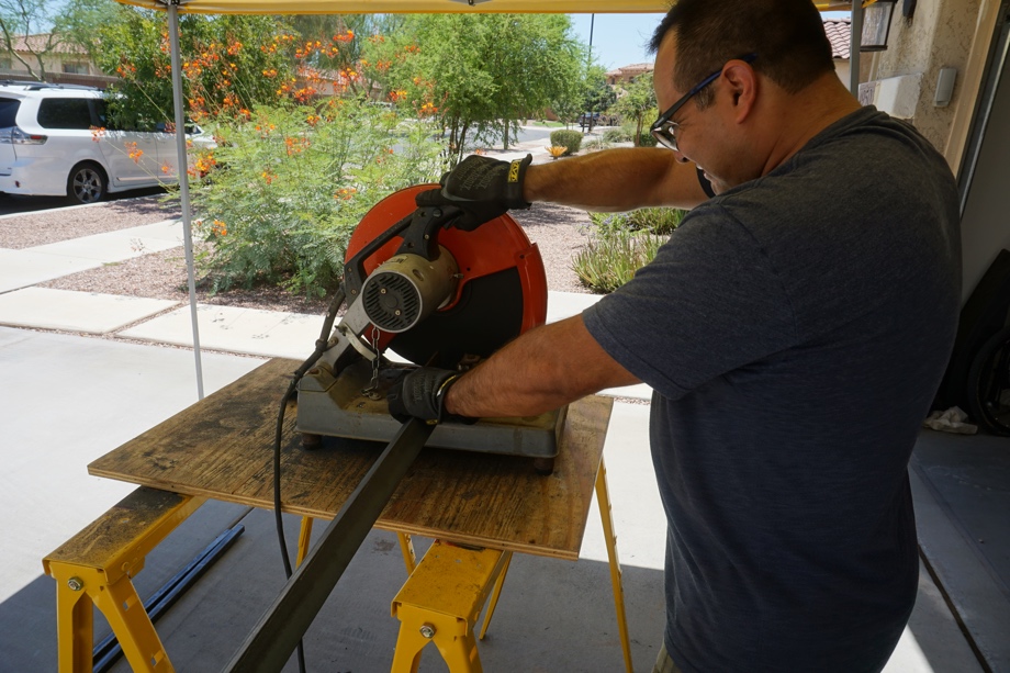
Then, we drilled holes through it that will eventually be for bolting it through the floor of the bus. 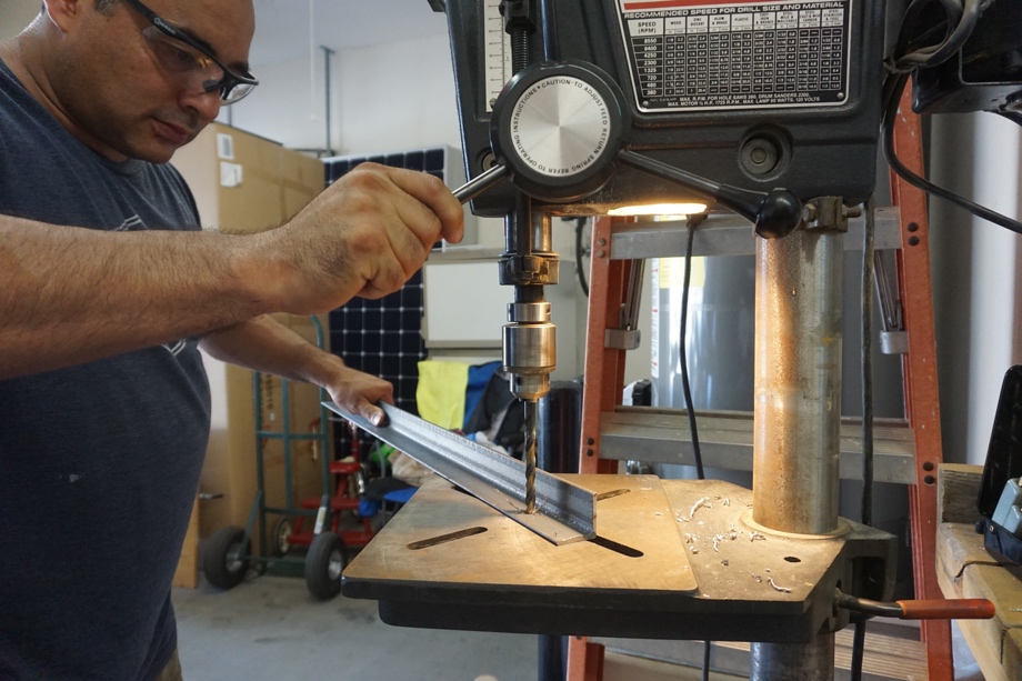
Next, we cut a sheet of plywood that will rest on top of the angle iron for the lower battery bank to sit on. 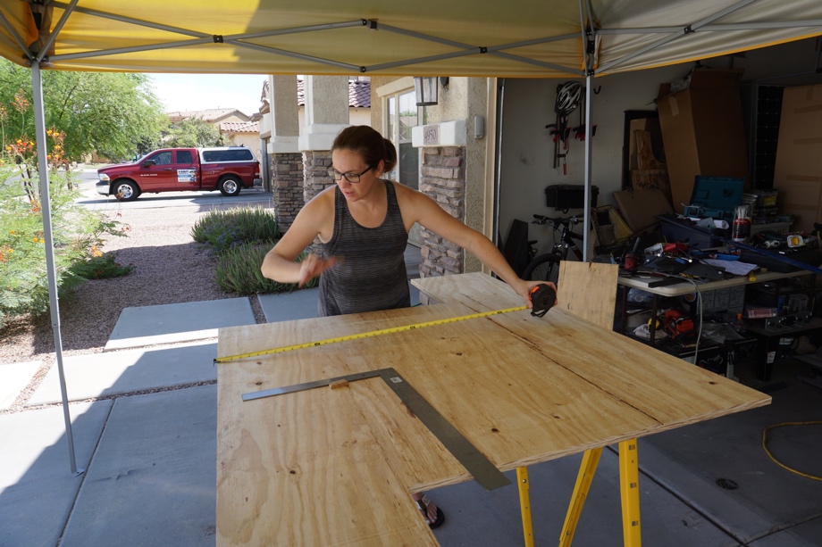
Then, we cut and welded a piece of 1.5” square tube to each outer corner of the angle providing the structure and support for the upper level of the stand. 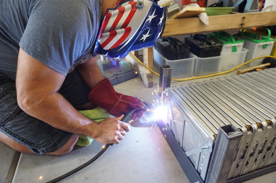
On the far side of the stand (the driver’s side once it’s in the bay), we welded a piece of 3/16” flat steel to the two corner tubes. We cut two holes through the flat steel to allow the nuts and threaded rods that hold the battery modules together to fit right in. 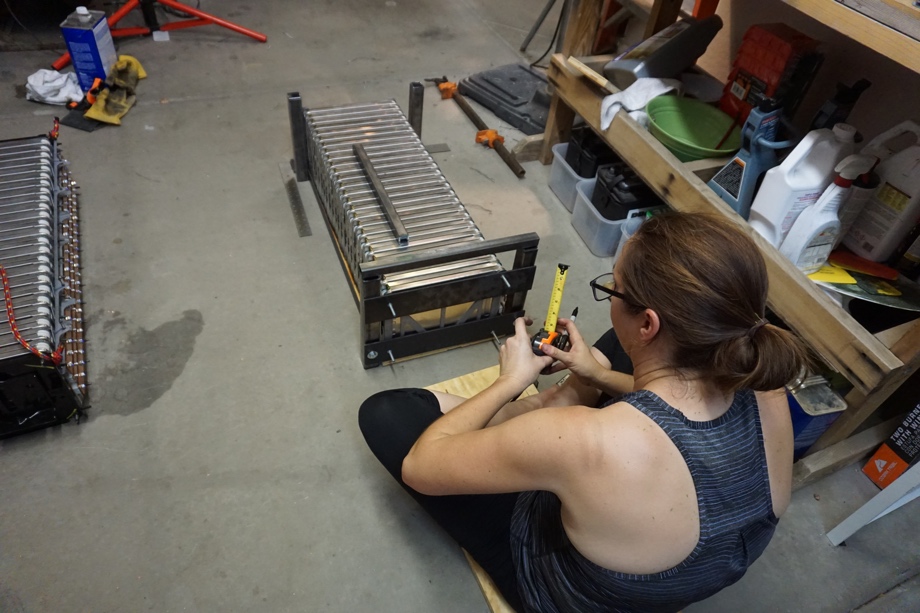 This will prevent the battery from slipping side to side. On the near side (the passenger side, which is the side we will slide the battery in from), we prepared two flat steel pieces with those same types of holes in them for the threaded rods and nuts. However, on this side, we will bolt the flat pieces onto the corner tubes once the battery is in place. This will very slightly compress the battery bank to the exact compression it was from the factory and will hold the entire bank in place. Bottom level finished.
Next came the build of the top of the stand. This is the really important part. The structure has to support the 200 pounds that will be sitting on it. It also has to sit at the exact right height, because we are basing the entire height of this off being able to bolt some tabs sticking off the back of the upper battery to a piece of angle iron attached to the back wall of the bay. 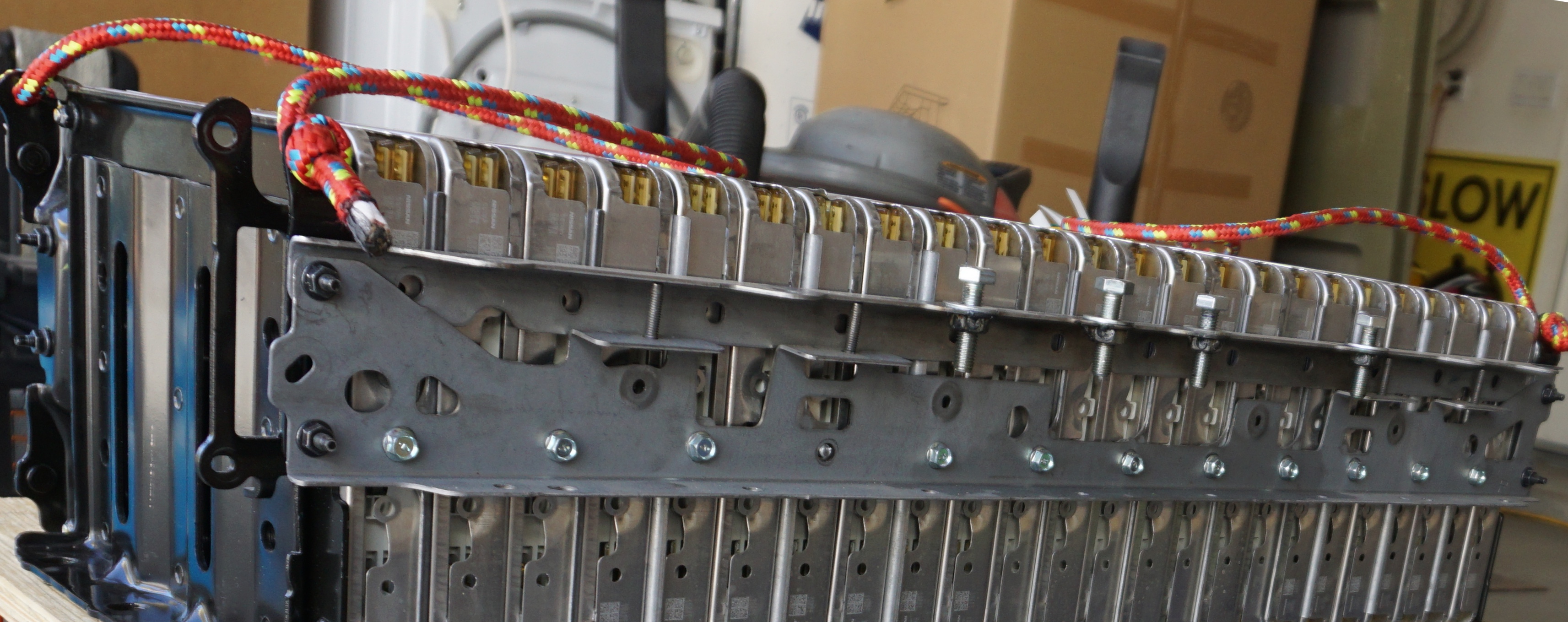
We probably double checked and tested this particular measurement about ten different times. 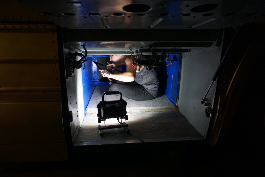 We had one shot to get this part right. If we messed up the height of the stand when we went to go put this whole thing in the bay with the 200 pound beast on top, it wouldn’t line up with that angle iron and we wouldn’t be able to bolt it down. We had to be sure this was right.
We cut more angle iron for the lengths of the upper battery and welded them to the top of the corner posts. 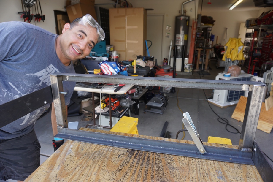
Then we used 1” square tube as “slats” between the two sides. 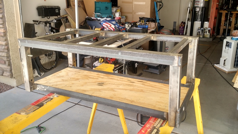
These were welded up underneath the angle iron. We cut another piece of plywood that will be screwed down to the top angle. The upper battery will then sit on that plywood. The framework of the upper battery bank has places that we can bolt it to the plywood on both sides and then to the angle iron on the back wall of the bay. 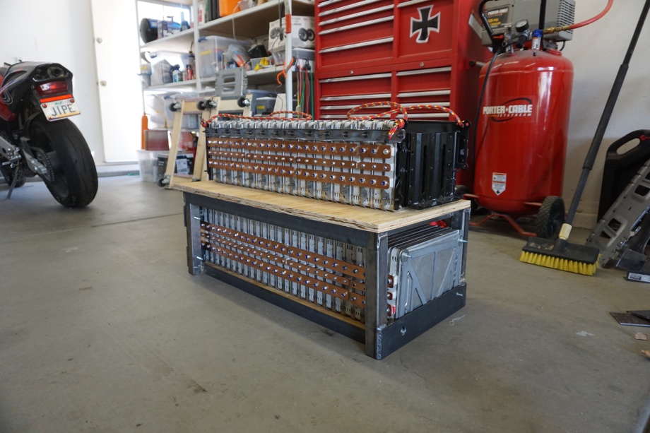
Finally, we decided to have the entire stand powder coated in orange. It will prevent it from rusting, and it just looks cool against our blue bay (and we get bonus points with our Denver Broncos loving son!).
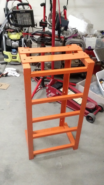
All in all, the stand turned out pretty well we think. It absolutely supports all the weight, and if we did all of our measurements correctly, it should line up just right inside the bay to be able to be bolted down and nothing should budge.
Next up in the battery series: BMS wiring, making cables to connect the upper and lower banks, and protecting all the bus bars, and finally getting it INTO the actual bus.
Check out the video:
Click here If you cannot see the video.

0 Comments
Comments powered by Disqus