


After fabricating a metal cage to protect the battery, we needed to tackle how to protect the exposed bus bars. Originally we were going to try to use some kind of plexiglass or clear acrylic to enable the polished copper to be seen. That proved to be too difficult. Besides, they were in a bay, likely behind a piece of wood, and after the novelty wore off, we wouldn't be looking at them much anyway. So we scratched that idea.
Before we could protect the terminals, we had to wire the battery for the BMS. When we first started this battery project, the BMS was one of the big questions we did not have a good answer for. We were not even EXACTLY sure what the function of the BMS was. I have provided some of the technical details at the end of this blog post (to save some of you from the super nerdy stuff).
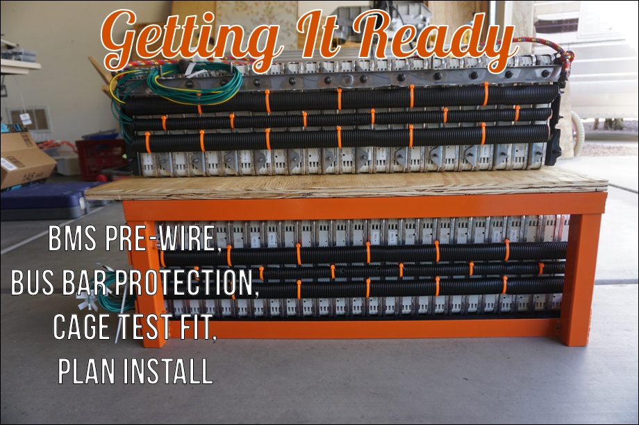
Wiring the BMS
The BMS requires a single probe (wire) into each "cell". In our case, a single "cell" is actually seven modules connected in parallel. Since the Nissan Leaf modules are each two cells in parallel and two cells in series (2S2P), our "cell" consisting of seven modules in parallel is actually a 2S14P configuration. The Leaf modules also offer a "sensing" port to access the voltage on each of the two internal parallel cells.
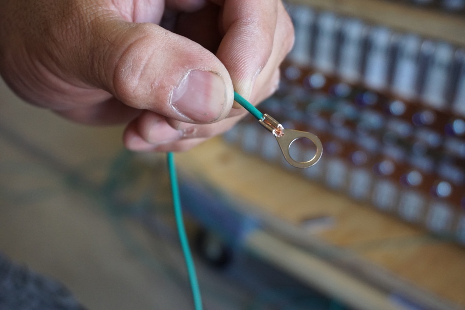
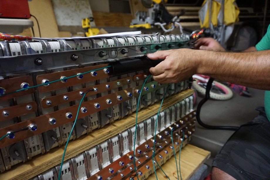
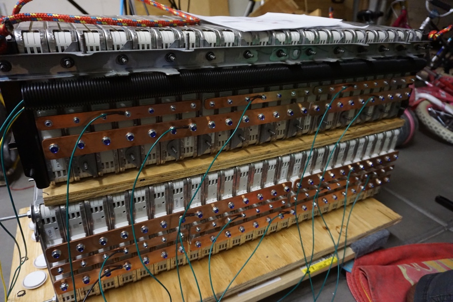
We used 18 AWG wire (as recommended by the BMS manufacturer) to wire the BMS. For no good reason, we chose to use green wire. To connect the wires, we crimped ring terminals to the ends and used the existing bolts to secure them to the bus bars.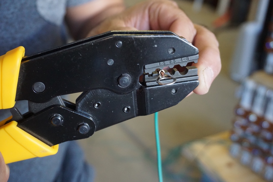
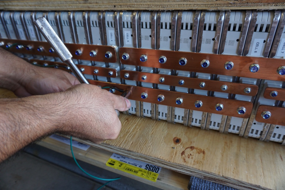
We labeled each one with a little flag that also served to cover the end of the wire and minimize the risk of a short. 16 wires in all: 1 to the negative terminal (a black wire of course), 1 to each positive post of each cell (14 green wires total) and an additional wire (yellow this time - should have used red but didn't have any) to the last positive post. The BMS we chose needs this highest value always on the 17th slot if we are using less than 16 cells (we are - we are only using 14). We wired it in such a way that all the wires would exit out of the "open" area in our bay. We took voltage readings all along the way to triple and quadruple check that we had everything wired and labeled correctly.
Protecting the Copper
It is pretty easy to see the potential danger with all those shiny copper bus bars exposed. A slip of a wrench or screwdriver could make for a very bad day (very realistically causing death). When this battery was in the Nissan Leaf car it was rated at being able to safely deliver " over 90,000 Watts". Simply applying Ohm's Law, since we have lowered the voltage of the pack we have drastically increased (by 7x in fact) the amount of current this pack can safely deliver. We needed a way to protect an accidental discharge.
Building the cage to keep the battery absolutely secure was a good first step. Now we needed to ensure that something accidentally coming in contact with the battery wouldn't cause a giant short. To be perfectly honest, there shouldn't be anything flying around in our electrical bay - but we want to make reasonable precautions "just in case".
We finally decided on a flexible black ribbed plastic designed for wire management. We happened to find it at Fry's Electronics while buying some wire connectors and heat shrink tubing. We brought some home and it seems to do a nice job of protecting the bus bars and looks pretty cool. Oh, and most importantly it doesn't conduct electricity. :)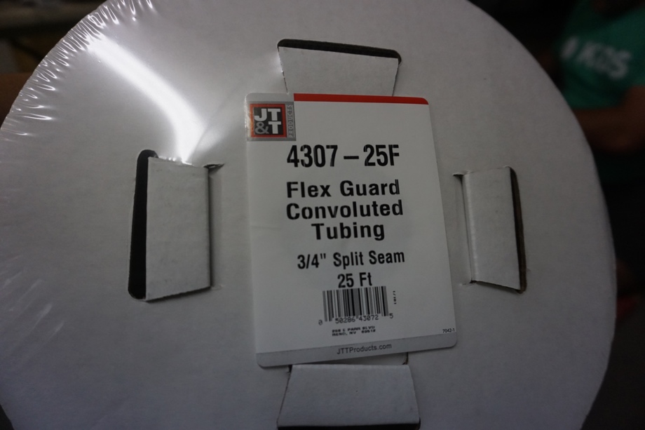
Test Fitting
One big problem remained. Our fully assembled battery with the cage is approximately 24 inches tall, but the hole that it needs to fit through is about 18 inches tall. Of course, our battery is in 2 pieces so there is SOME hope of being able to get it in there. To add to the complications, the battery weighs just over 400 pounds. We have trouble even moving the battery around in the vastness of our garage. We have added some rope to the top bank so we can lift it with that and hurt our backs instead of our hands. 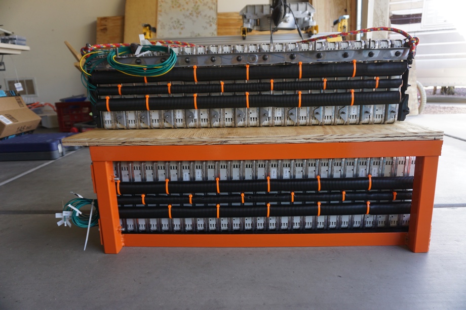
How in the world are we going to maneuver it to fit in such a small space? With leverage of course. Our kids are studying simple machines in some of our homeschooling science curricula - what a great way to show them how this works in action! So we test fit the banks on the cage, made careful measurements, and proceeded to conjure up a crazy plan. This plan includes a long 2 by 6 board that will act as a simple lever. A furniture dolly that will act as a "wheel and axle". Some leveling blocks to act as a "wedge". A couple pieces of sheet wood acting as an "inclined plane" and a car jack (not technically a simple machine - but hey that's enough science lesson kids, we actually need to get some stuff done). We describe the crazy plan in the video so be sure to watch and stay tuned to see if it actually worked!
Check out the video:
Click here If you cannot see the video.
And now, onto the super nerdy stuff!
BMS
What is a BMS? BMS stands for "Battery Management System" and, roughly speaking, they basically protect the batteries from damage. The way they protect the batteries varies from solution to solution, but they all usually provide protection from over voltage, under voltage, and often overheating. As seen in recent news reports about cell phone fires, lithium batteries have the potential to be unstable under certain conditions. We are basically sleeping on top of these batteries; we certainly don't want that!
Cell Over Voltage
One thing that needs to be monitored pretty closely is a lithium battery's top voltage. With the chemistry of the Nissan Leaf battery, this tops off at 4.2 Volts. From what we have read from several sources, it is much easier on the batteries if you limit this to something like 4.1 or 4.15 Volts. The danger is if this value goes over 4.2 volts the pack could be damaged and exhibit some poor behavior (like puffing up and catching fire). The problem is that it is almost impossible to detect this if all you are measuring is the entire pack's voltage. As the batteries age, there is a very high probability that some of the cells will deteriorate faster than others. So while some cells could be at say 3.8 Volts, other cells might be at something like 4.1 Volts - dangerously close to the limit for the chemistry, but you wouldn't know it unless you had a probe in each cell. That is exactly what most BMS systems do; they put a probe in each cell to measure the voltage at that cell. The BMS constantly monitors each cell voltage and instructs the battery charger to stop if any of the cells reach the threshold (4.1 Volts in this case) and shut the system down if the emergency threshold is reached (4.15 Volts in our case).
Cell Under Voltage
The cell under voltage is very similar to cell over voltage except at the bottom of the range. Lithium-Ion batteries can easily be damaged if they are allowed to be depleted too far. Even radio control toys and cell phones have circuits that turn these devices off before the Lithium-Ion batteries can go below a certain voltage (3.2 Volts in our case). As with the over voltage, there is a very real possibility that one of the cells could reach this critical point before the other cells, and the BMS needs to have the ability to "turn off" anything drawing power from the battery to prevent damage until that battery is charged again.
Overheating
As batteries charge (especially at higher Amperage rates), they produce heat. Heat, of course, is the enemy of batteries. Overheat protection simply limits the current (or shuts it off) when the batteries become too hot and there is potential for damage.
Other Features
There are a number of other features besides these "core" features that we considered when deciding on a BMS solution. Here are a few of the others we considered and evaluated before making our choice.
Internal Resistance Monitoring
Internal resistance monitoring can give you a very good indication of how the battery is aging. As batteries age, they begin to break down, and an increase in their internal resistance can be measured. Very often a battery's "health" can be determined by the internal resistance of the batteries.
State of Charge (SOC) Calculations
Most accurate state of charge calculations on BMSs involve a "shunt". A "shunt" is basically a high precision resistor which can be used to observe current flow. These little devices can very accurately track how much current flows in and out of our system. Based on some input parameters (like how much capacity your batteries have, what type they are, etc), a shunt can give you a very accurate "percent full" (state of charge) of your batteries.
Cell Balancing
Many BMS solutions are now offering cell balancing. They have different variations on how they do it, but they all basically try to detect if a cell's voltage is some threshold higher than the other cells. Ideally, all the cells would be the exact same Voltage. Once this "high" cell is detected a resistance is placed across this cell to "drain off" some of the energy in that cell until it comes back into spec.
CAN Bus Communication
Many of today's more advanced inverters and power accessories communicate to one another via CAN bus similar to how modern automobile computers communicate. Each manufacturer seems to have their own proprietary standard, but many of the BMS companies are working with them to communicate with their equipment.
Dedicated LCD Displays and Information Trackers
Most of the BMS solutions offer some sort of "control panel" where all the geeky information like cell voltages, cell temperatures, current loads, state of health, and state of charge can be seen. In addition to seeing the current data, many BMS solutions offer some kind of logger to see how this data has done over time.
Our BMS Choice
We found two really great solutions for our battery. The first one was from Orion BMS and it seemed like a really solid product. The other was from REC. I think either of these two would have really been great for us. I wrote each of them an email explaining our situation - what type of battery we are using, what inverters we are using, MPPT solar charge controllers etc. They were both very prompt and helpful with their responses, but the REC-BMS guys seemed more "in tune" with what we were doing. Their answers were much more specific and they just really went out of their way to fully answer my questions. The Orion guys really felt more like they were targeting the EV car market, and the REC BMS guys were more in the "off grid" and "boat" camp.

0 Comments
Comments powered by Disqus