


We are nearly done plumbing the major supply pieces in the water bay, but we had to finish up a few things before we could move inside the bus.
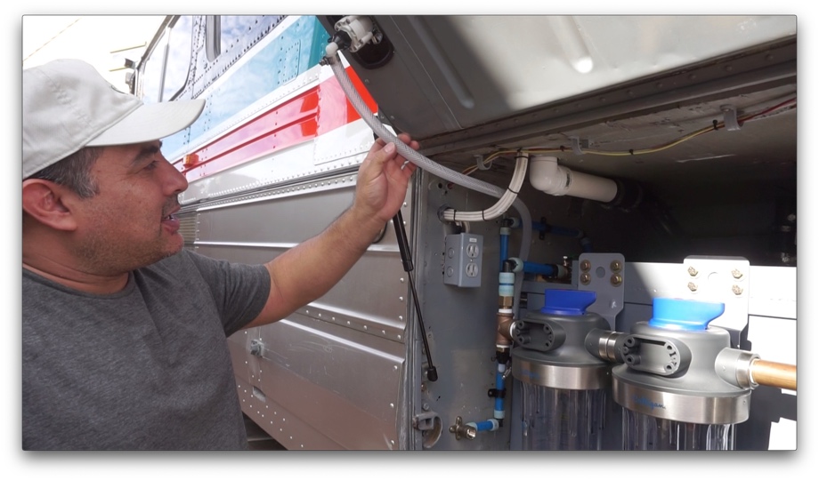
First up was putting in a hose between our water inlet in the side of the bus and the inlet fitting to our water filters. They are both ½” fittings, and we wanted to have a true ½” hose connecting them. We decided to use food-grade braided vinyl tubing. Because our inlet is in our bay door that has to be able to lift open, we left slack in the hose so that it gently curves and bends out of the way when the door closes.
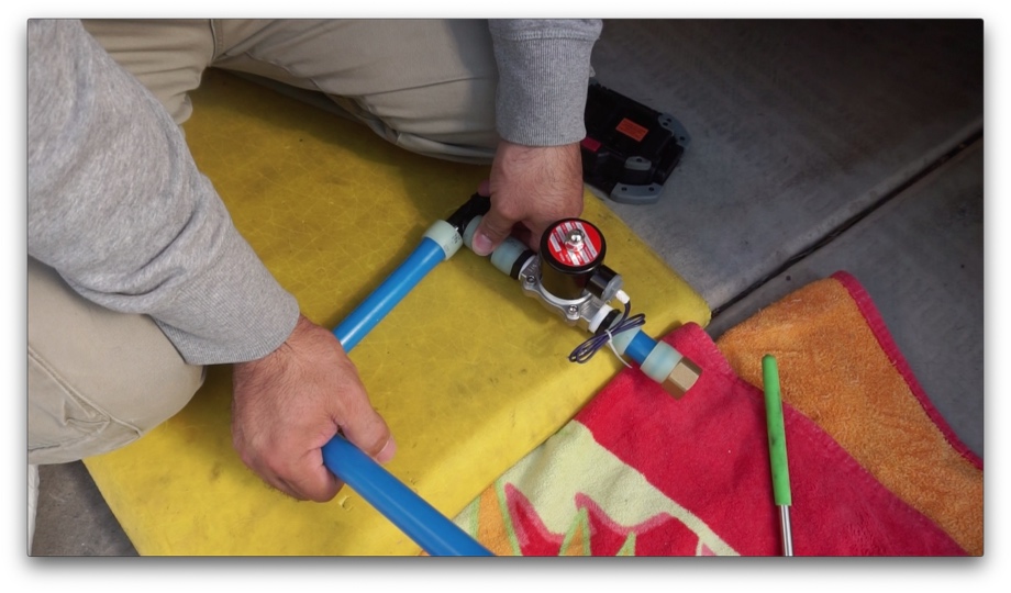
The next project was to plumb in the fresh-water tank fill. We have a 1” FNPT inlet to our tank that we plumbed with a brass elbow. Instead of putting in a manual valve on the city water line (to either fill the tank or bypass the tank and go straight to the manifolds), we chose to go with an electronic 12V solenoid valve. The reason we chose this type of valve is to allow us to sync it up with our home automation. If we are hooked up to city water but would rather just fill the tank and run off our pump (maybe the RV park has poor or inconsistent water pressure), having the automated fill valve will allow us to tell it to automatically use the city water to top off the tank if the water level in the tank drops to a set parameter (for example keep it between 40% and 60% full). We won’t have to keep monitoring the tank level or go in and out turning on and shutting off the water. The automated valve will keep the tank at the preset level.
We aren’t too sure how often we will encounter RV parks with poor water pressure where we want to run off our tank and pump instead, but this will allow us to do that just in case. We can still bypass the tank and run off the city water pressure most of the time when we are hooked up if the pressure is good.
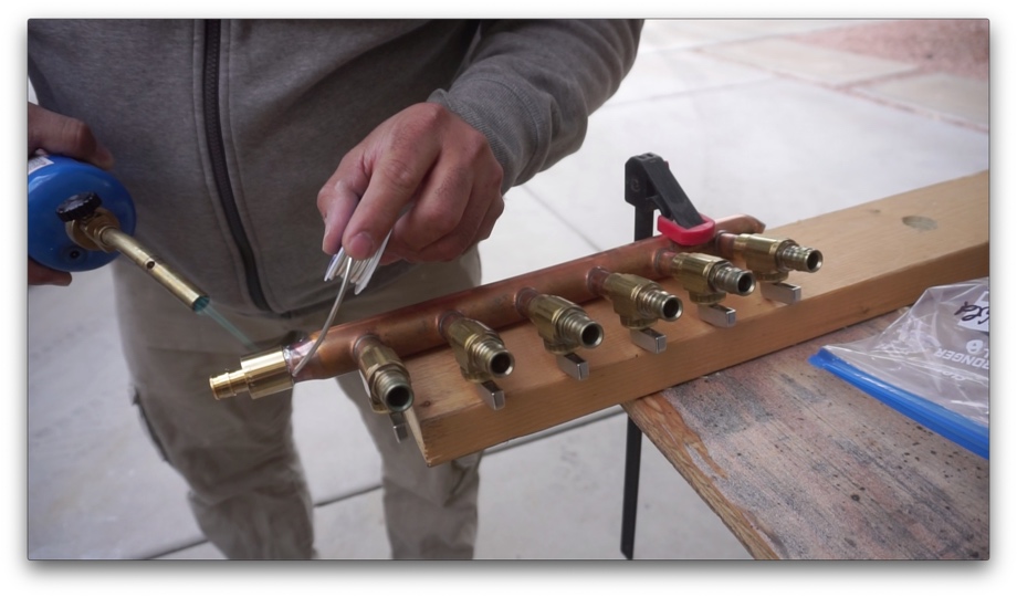
The last project was to solder on the fittings to the ends of our two manifolds. We were sure to sand and clean the ends very well so we could get a good connection. Juan then painted on the flux, brought out the torch, and soldered the fittings on. Then, he decided he couldn’t stand the “patina” of the copper manifolds and polished them. He just couldn’t help himself. About 20 minutes or so of work, and both of the manifolds shined right up.
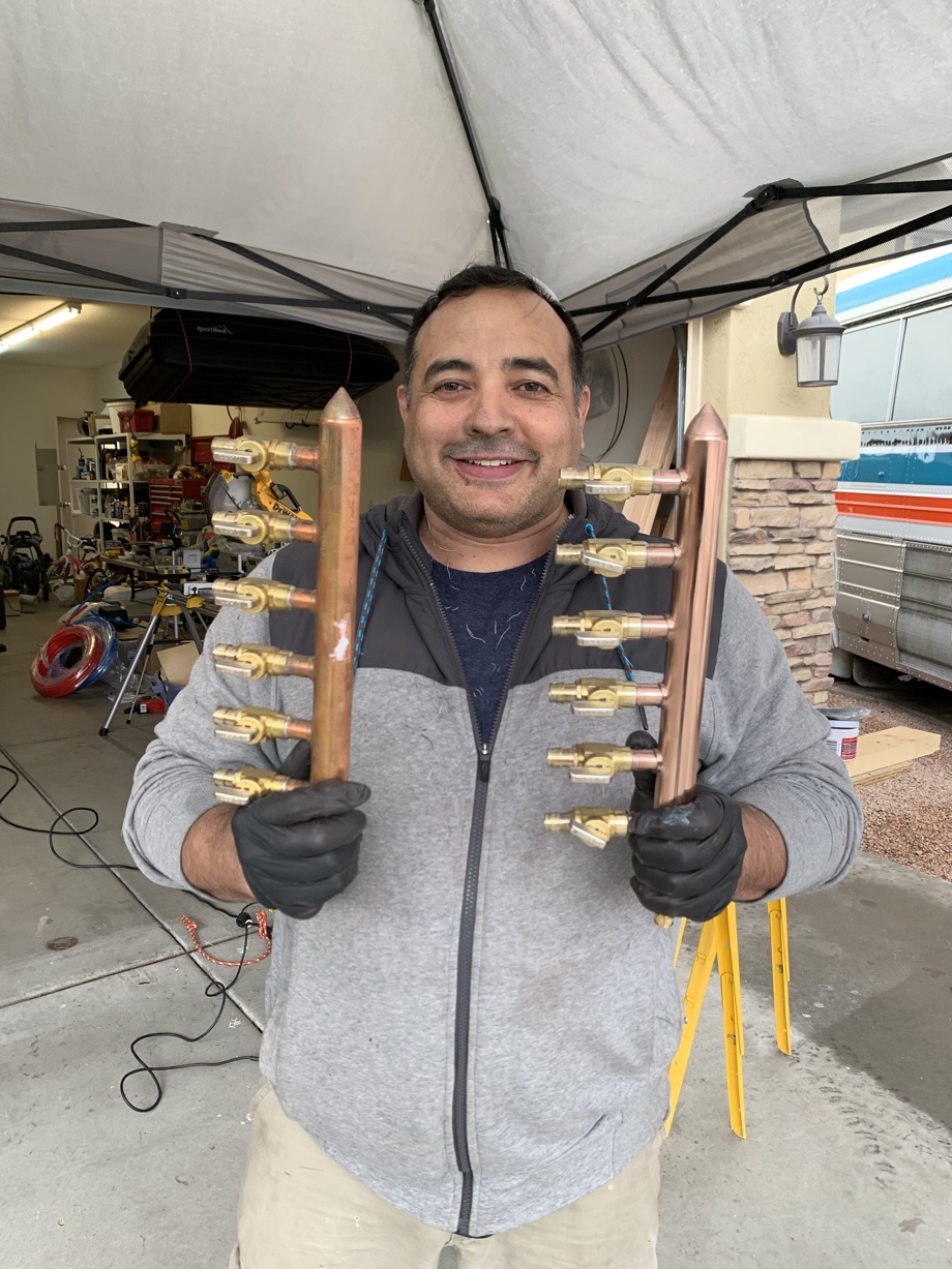
We still needed to connect the manifolds to the hot and cold Pex lines running from the pump and water heater, but we decided to hold off on that. First, we would need to get the Pex lines run from the manifolds into the bus for each of the fixtures inside. That would help us to be sure the manifolds were positioned correctly before we make that final water connection to the manifold inlets.
However, before we ran Pex lines into the bus, we wanted to get some of those water fixtures in place in the bus so we would know exactly where the Pex lines needed to end up. That’s what’s coming up next: we head inside and start the very beginnings of the kitchen.
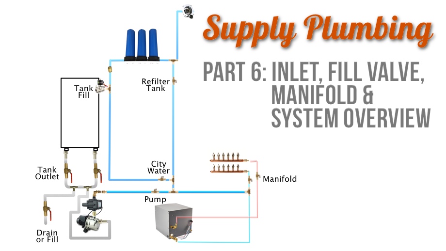
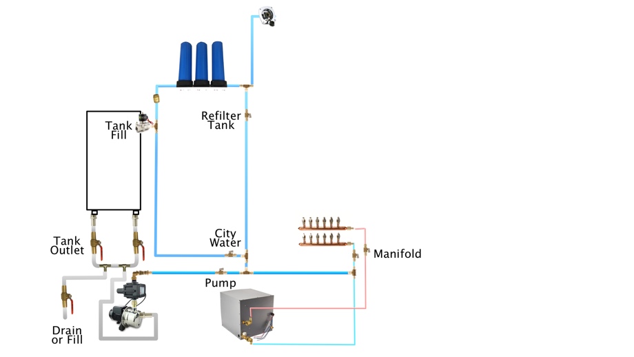
System Overview
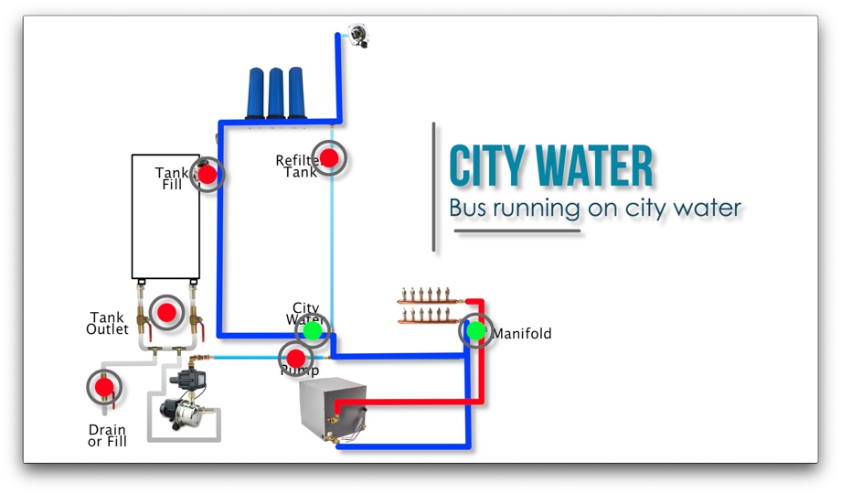
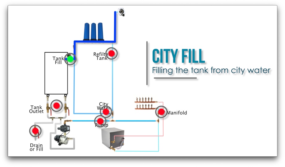
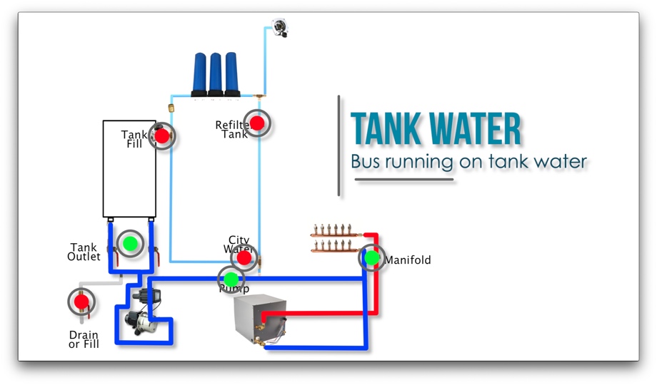
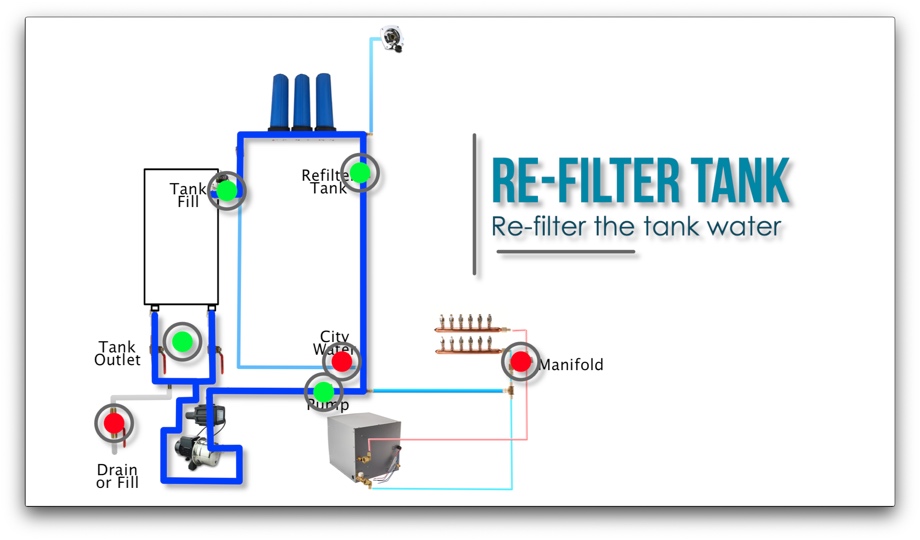
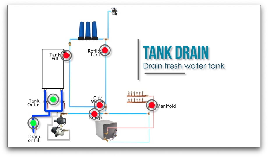
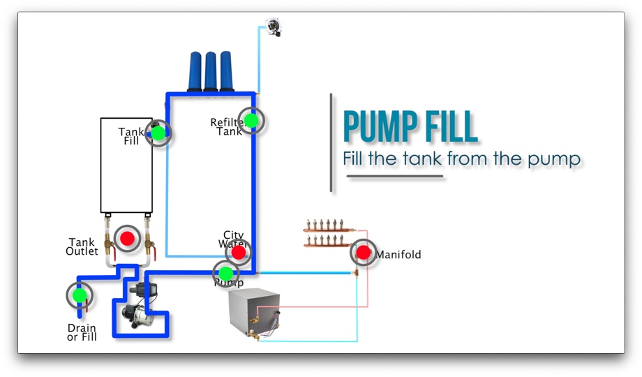
We thought that this would be a good point in our plumbing to stop and give a brief overview of the system we designed. In the video, we talk through this. Here on the post, however, we will simply post some designs that show all the parts and pieces and how they work together. We also include how we can open and close different valves to configure the system for different needs.
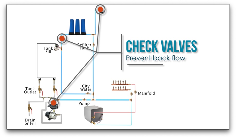
Check Valves
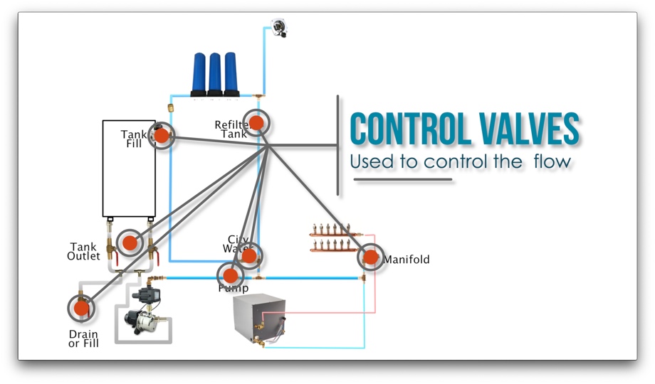
Control Valves
Running on City Water
Filling the Tank from City Water
Running on the Tank and Pump
Refiltering the Tank
Draining the Tank
Filling the Tank from Bladder or Low Pressure Water Source
Watch the video:
Click here If you cannot see the video.
Parts we used
BACOENG Stainless Steel Shallow Well Pump
RV Tankless Water Heater by Girard-GSWH-2
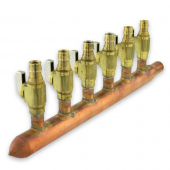 6 branch Copper Manifold 1/2" PEX-A
Ronteix 4-Ply High Peformance 90 Degree ElbowL
1/8" Rubber Flooring
CULLIGAN WH-HD200-C Whole House Water Filter
SHURFLO Chrome 183-029-14 Pressure Reducing City Water Entry
Dewalt Pex Expander Tool
PEX Tube Cutter
Uponor 3/4" PEX-a blue tubing
Uponor 1/2" PEX-a red tubing
Uponor 1/2" PEX-a blue tubing
Uponor 1/2" PEX-a Ring with Stop
Uponor 3/4" PEX-a Ring with Stop
Uponor 3/4" PEX-a Elbow
Uponor 1/2" PEX-a Elbow
Uponor 3/4" PEX-a TEE
Uponor 1/2" PEX-a TEE
Uponor 3/4" 3/4" 1/2" PEX-a TEE


0 Comments
Comments powered by Disqus