


We finished the first part of the insulation (Ceratex) and the furring strips. Before we could move onto the rest of the insulation (Roxul) or putting up any structure, we had to get the wiring in place for all of the overhead lighting.
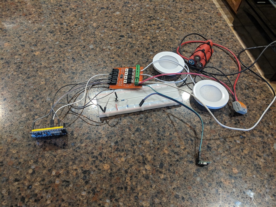
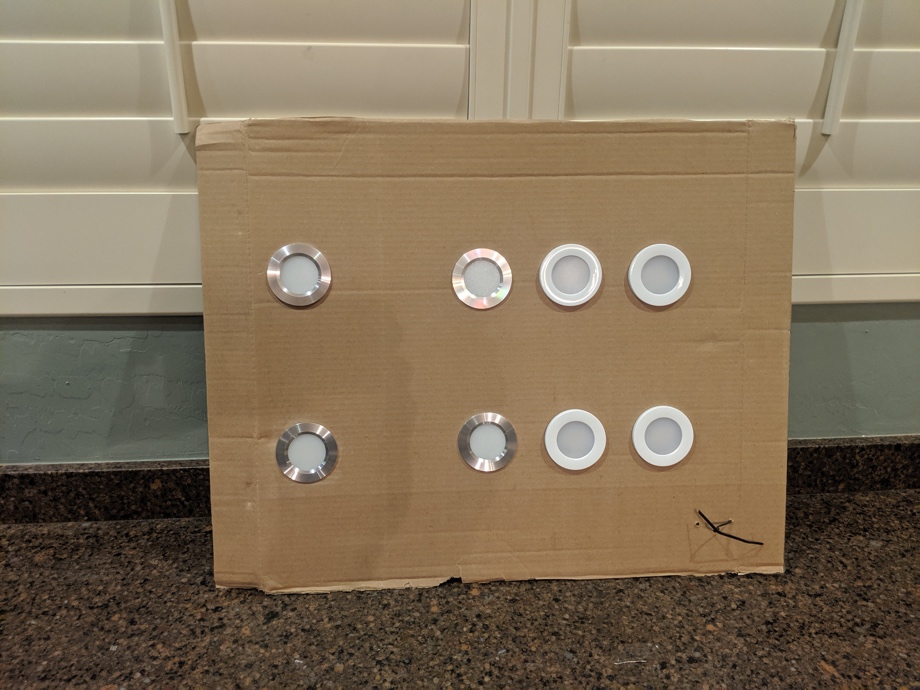
When we last shared our progress with “bus automation”, we shared a little bit about the plans for overhead lighting. As with most things, we tend to overbuild, and lighting has been no exception. We are putting in a lot of overhead lights. I suppose our perspective is something like this - you can always turn some lights off (or even dim them) if you feel like it’s too much, but if you don’t have enough lights, then it's difficult to make it brighter. We even practiced different numbers of lights. We stuck some of our lights in a piece of cardboard, temporarily wired to a 12V source, and moved it around different locations inside the bus at night to see if it felt like the right amount of lights, too many, too few, too close together, too far apart, etc. After that little experiment, we came up with a plan for light locations and spacing.
Next, we had to imagine how we would want them to function in our daily life. For example, if we are working in the kitchen at night after the little kids are in bed, I may only want the lights over the countertop on, but not the ones that are in the kitchen in front of the pantry. Or if Juan is up working later than I am, maybe only two of the eight living room lights should be on for him to work while I am sleeping. If we are watching a movie with the kids at night, maybe we want to turn off certain lights to avoid a glare on the screen.
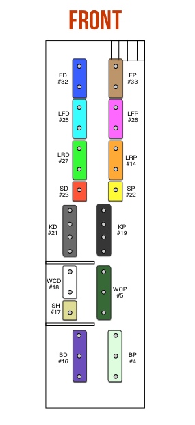
In order to have more control over the lights, we decided to create zones. Not just living room/kitchen/bathroom/bedroom. But, we have front driver’s side of the living room (2 lights), rear driver’s side of the living room (2 lights), front passenger side of the living room (2 lights), rear passenger side of the living room (2 lights). Or we have driver’s side of the kitchen (4 lights), passenger side of the kitchen (4 lights). Plus more zones for the driver's area, kids' seats, bathroom, bedroom. The lights in each zone will be controlled together but can function independently of the other zones. We can also group zones together to make switching easier, but make changes to the individual zones through our phones, etc.
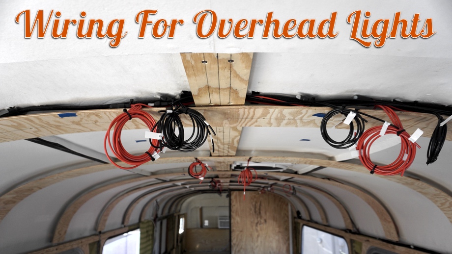
Although it seems like this is complicated, the wiring for it actually is very simple. The lights are switched on the negative side. That meant that we had to run a separate negative wire for each zone from the location where our lighting automation control center will be (behind the driver’s seat). Once we had a negative wire to each zone, the lights within that zone can have the negative wires daisy-chained together. We used 14 AWG pre-tinned marine cable (black) for this wiring. Again, we like to oversize our wires and use good quality wire made for living in moving environments. To wire the positive side, the lights all can share a common wire. We decided to run one main 10AWG wire down the side of the bus in our wire run. We simply branched off of that in locations that made sense using the 14AWG marine cable (red) and daisy-chained lights together.
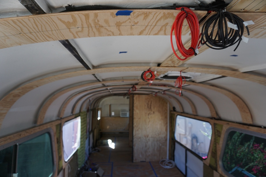
When we put up our furring strips, we discussed that we left small gaps between strips so we would have places for this 14AWG wire to run for the lights. This worked out great as we ran all the wires to the locations we have planned for the lights. We were sure to leave ourselves plenty of extra length of wire in each location in case we have to move a light forward or backward or to the side when the time comes to actually install the lights themselves. For now, we simply looped all the wires up and out of the way, making sure to label each one so that we know what’s what when we finally get the ceiling installed and are ready to put in the lights.
 The last wiring for this project was to run the wires for the switches. Because of the automation, these are not traditional switches that need wires run back and forth from the actual lights. Technically, we don’t even “need” to have switches. We can control everything with our phones. But, we still want the ease of just walking in and hitting a switch. It makes the most functional sense. We just like the control and easier wiring that the automation allows. So for wiring the switches, all they need is a signal. That means we can simply run a network cable to each location we want switches. We are using a CAT 6 cable to run from our lighting control center to each of our switch panels - one by the front door, one in the kitchen, one in the bathroom, and one in the bedroom. We will use small momentary switches to simply push on and off or hold down to dim/brighten.
We are pretty excited to see how this will all work out when we actually get the lights in. That may be a bit, however. Because of the way we have decided to build interior walls and the ceiling, the walls will come first. That means that what’s coming up is building structures like our pocket doors and closet. With this wiring done, let’s move on to some woodworking.
Watch the video:
Click here If you cannot see the video.
Products we used:
1/2" Dual Wall Adhesive Marine Heat Shrink Tube
3/8" 20ft Dual Wall Adhesive Marine Grade Heat Shrink Tube
Cat 6 cable (100ft)
Closed End Crimp Terminal, Nylon Wire Connector, Tin-Plated Copper Core, CE8, 8-6 Gauge
Closed End Crimp Terminal, Nylon Wire Connector, Tin-Plated Copper Core, CE5, 12-10 Gauge
Our light switches
Small zip ties


0 Comments
Comments powered by Disqus