


This has been updated: please see the update here
In our previous episode in this series, we installed and secured the Nissan Leaf battery. Now we connect all the components to ensure safe power delivery to our systems. At the bottom of this post, we provided a list of all the components and tools we used in this build-up (some contain affiliate links).
The Nissan Leaf battery will be used to power all the 12V "house" systems (lights, pumps, fans, USB chargers, stereo etc) as well as provide power for all the 110V appliances (air conditioner, microwave, electric cooktop, refrigerator, outlets). The details of both of those systems will be posted down the road as we get to each system. For now, we are focusing on safely getting power out of our battery and ready for systems that need to use it. For clarification: this battery is not used to start or run the bus in any way. The bus has its own 12V system and batteries that it uses to start the bus and also operate all of the bus lights, etc.
We will have two ways to charge the Leaf battery. First, the Victron Quattro inverter has a built-in charger that will charge the battery via the shore power or a generator. Second, we plan to have a fairly large solar array that will directly charge the battery. Currently, we do not have a plan to wire a charger off the bus's alternator, but if we find a good solution that could change. :)
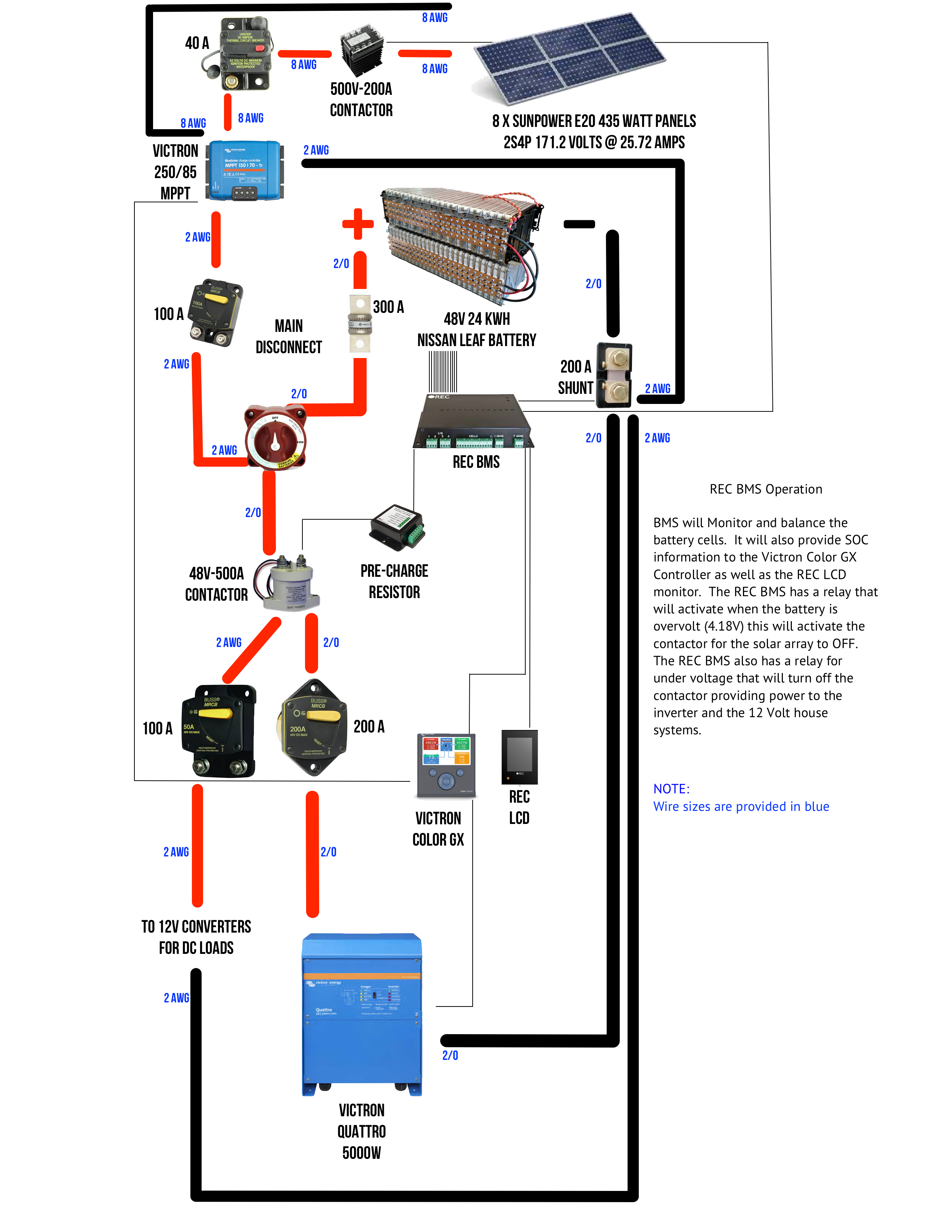
In order to send the battery power out into the bus, we needed to make a system chart to determine what safety components we needed. We created a diagram of what we thought might fit our power requirements.
In general terms, we put a fuse/breaker in the line anywhere power was coming into the system. The breakers will also be a good way to isolate sections of the system if we ever need to work on one particular part. The large main on/off switch (the red square in the center of the diagram) will allow us to shut off the entire system. There is also one "catastrophic" fuse, a Class T 300 Amp fuse, that will protect the entire system in the event of a major battery malfunction. On the negative side, there is a shunt that sends information on the battery usage to the BMS, which will allow us to monitor the state of charge. If the BMS detects any problems, it will shut off the system via the 48V-500Amp contactor. We provided wire sizes for each of the major components and sized the breakers to fit the given wire sizes. After modeling it, we sent it to a few friends to review and comment on.
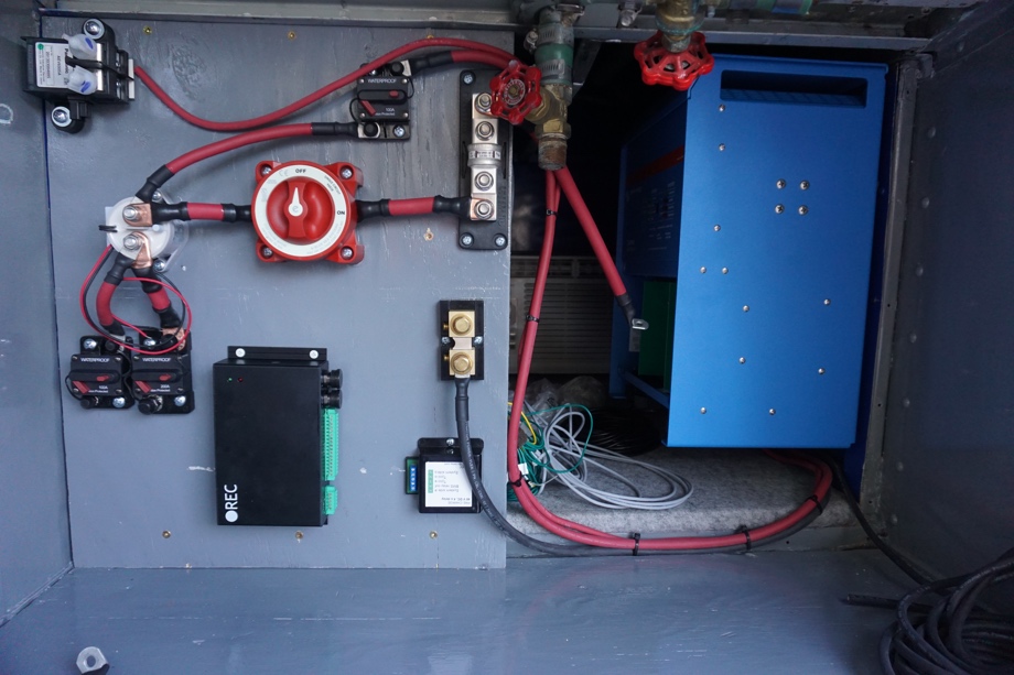
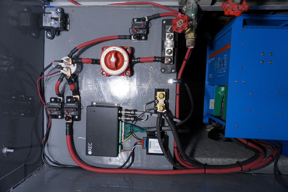
We decided to build a "wall" in front of the battery with a piece of 3/4" plywood (painted to match, of course) to house all the components in an easily accessible location.
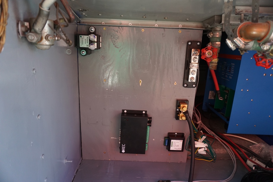
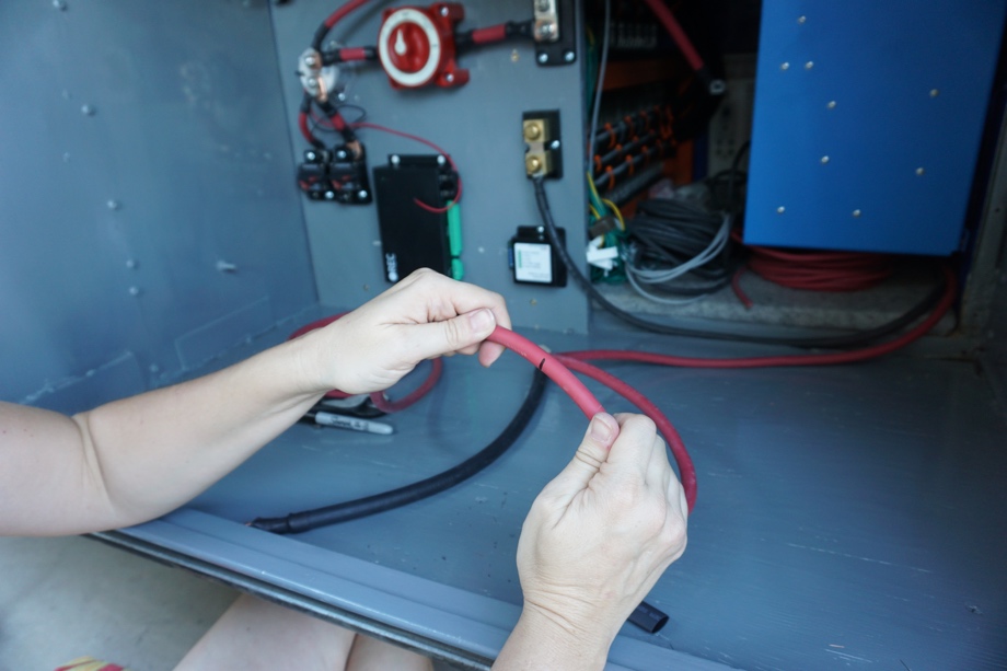
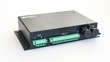
We secured the components to the wall and created custom wires for each connection.
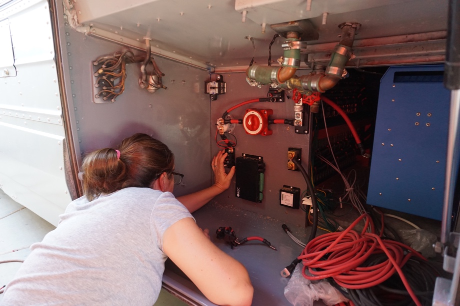
Next, we made more custom wires for the major components - the inverter and charge controller.
The most tedious part (it took us nearly all day) was wiring the BMS with all sixteen of the wires we made in part 4. Check out that post to learn more about what a BMS is or does.
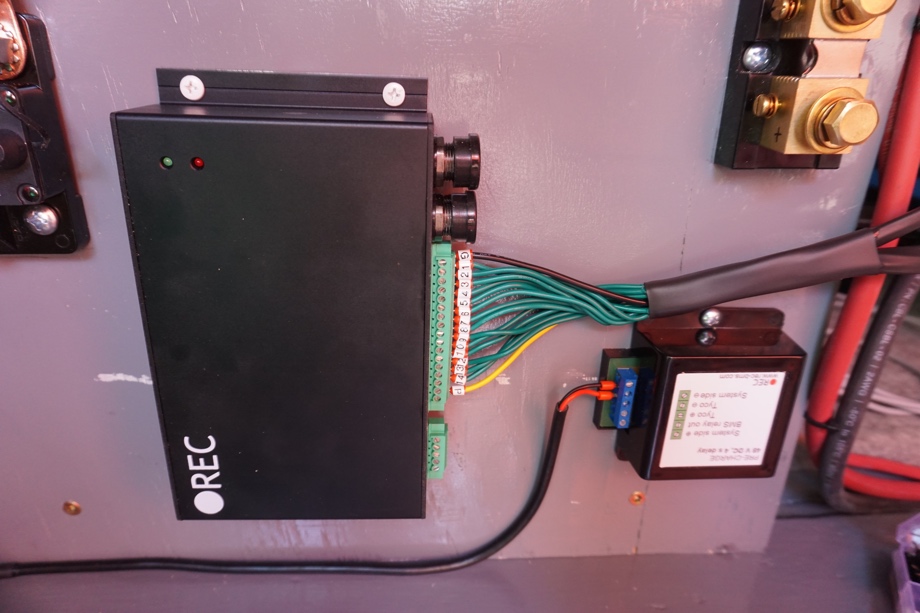
Finally, after wiring the main switch, fuse, breakers, and BMS, we were able to connect the pre-charge controller, the shunt, and the temperature monitors for the BMS.
One part we are still not 100% sure about is the secondary contactor (the 500V-200 Amp one) coming from the solar panels. The BMS has a way to control it with a programmable relay. I have been in communication with REC-BMS about it. The theory is this: the "main" contactor would be used (48V-500A one) as the primary "on/off" mechanism for the BMS. If something goes wrong, that contactor gets shut off and an alarm sounds. IF this happens because of a low battery situation, the setup I have detailed in this diagram would still allow the solar panels to charge the battery.
We are still not finished with wiring for the solar panel portion of the diagram, including that contactor and the breaker. We found out that the breaker we ordered on Amazon was coming from China, so it took quite a while to get here. After we make a final decision about the 200 Amp contactor and add in that breaker, we will follow up with another post.
If you have any specific questions about the system or components, be sure to leave a comment.
This has been updated: please see the update here
Watch the video:
Click here If you cannot see the video.
Parts We Used
 REC BMS
2/0 Wire
2 AWG Wire
8 AWG Wire
Small ferrules
Larger ferrules
Blue Sea Systems Class T 300 Amp Fuse
Blue Sea Systems Class T Fuse Block
Blue Sea Systems E-Series Switch
T Tocas 200 Amp DC Circuit Breaker
T Tocas 100 Amp DC Circuit Breaker
Langir 250 Volt 40 Amp DC Circuit Breaker


Tools We Used
Small Crimpers
Big Crimpers


0 Comments
Comments powered by Disqus