


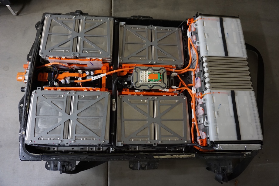
When we last left off, we had cracked open the battery housing and were planning on configuring our 2013 Nissan Leaf module into sixteen 24-Volt batteries. The original plan called for 24-Volt configuration because each of the Nissan Leaf modules is configured with 4 cells, 2 joined in parallel and 2 joined in series. Since each cell is 3.7 volts nominal, there is not a great way to join the modules to make a 12-Volt battery. A little more research revealed that a 48-Volt configuration might be a better fit.
Watch the video here:
Click here If you cannot see the video.
Caveat emptor: This article gets very technical. I could not find many technical details on using Nissan Leaf Modules when I started this project, so I have done my best to include the details for anyone else considering using a setup like this.
How Did We End Up Choosing a 48 Volt System?
Module Configuration
Not going 12 Volts was a pretty easy decision because the Leaf modules did not lend themselves to being configured that way - you can't put 1 1/2 modules together. The next logical choice was 24 Volt since it could be obtained by fitting 3 modules in series (6s2p configuration for a working voltage range of 19.2V to 25.2V). The unfortunate part about the 3 module configuration is that 19.2 Volts is a little too low, but switching to 4 modules for 33.6 Volts is a little too high for the 24V inverter that we were looking at. 3.5 modules would be about perfect. 7 modules in series are just about perfect for the 48V inverter that we have been researching. This gives us operating voltages between 44.8 Volts and 58.8 Volts.
Much Higher Amperage Loads = Much Higher Costs
This configuration offered other benefits, like increased efficiency as well as the ability to run smaller wire and fuses. I have often heard the expression "wires carry amps not volts", but I never fully understood what that meant until I started researching the different battery configurations. The inverter I have had my eye on is rated for 5000 Watts with a surge capability of up to 10,000 Watts. In a 12-Volt configuration at full capacity, this would pull about 417 Amps and 833 Amps as a surge load! To carry this kind of load you would need 3 or 4 4/0 (#0000) gauge cables which are HUGE (and very expensive). Of course with higher Amperage and wire sizes also comes more expensive fuses, switches, etc. Adjusting the voltage to 24-Volt drops the wire size requirement in half and taking it to 48-Volt drops the wire size again by half. So on a 48 Volt system at full capacity, the system would be pulling 104 Amps and 208 Amps at a maximum surge. Even the surge power can be handled by a single 2/0 (#00) gauge wire (which is still huge but much more manageable).
Solar Considerations
Finding our solar panels solidified our decision to go with a 48 Volt configuration. Initially, we thought that the solar system would be a significant challenge to fit with a 48-Volt system. We had been under the impression that most solar systems are setup to run primarily as 12-Volt systems. This did not prove to be the case at all. Finding panels and charge controllers for a 48 Volt configuration was not only easy - it was cheaper and much easier. We plan on having just under 3500 Watts of solar mounted on the roof (8 panels @ 435 Watts each). In a 12 Volt configuration, this would have required 4 large and expensive charge controllers and at least 4 times as much cable. Going to 24-Volt allows the use of two controllers, and 48-Volt requiring only a single charge controller (we settled on the Victron BlueSolar MPPT 150/70 charge controller). Each charge controller costs about $600.
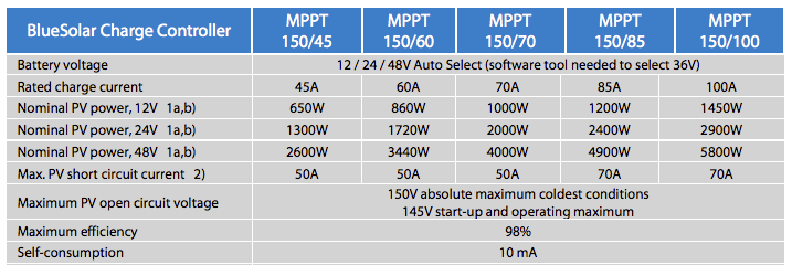
Notice how much more PV power each given charge controller can handle as the voltage increases.
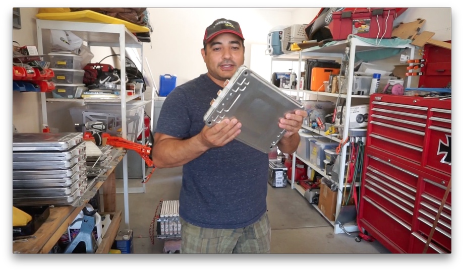
Reconfiguring the Modules
After we decided on a 48-Volt battery, it was time to reconfigure the Nissan Leaf modules to give us this voltage. The Nissan Leaf Battery comes with 48 modules. Each module has 4 cells (2 in series and 2 in parallel), making a module's voltage a nominal 7.4 Volts @ 66.2 Ah.
In order to achieve 48 Volts, 7 modules need to be connected in series (7.4V X 7 modules = 51.8V). Since the Leaf comes with 48 modules, we could have used 42 modules (making 7 "6-module packs"), but that would have left us with six "extra". The other option was to buy one more module to have 49. This would allow us to make 7 "7-module packs". We decided to buy an extra module off eBay (it ended up costing about $140.00 for the single module). This allowed us to keep the full 24 kWh capacity of our battery (7 modules * 66.2 Ah * 51.8V = 24004.12 Watt Hours).
The final decision was whether to put the "7 module packs" in parallel then tie them in series or to put the "7 module packs" in series then tie them all together in parallel. The latter offers the advantage of if a module goes bad you only lose 1/7th of your capacity and you can remove the "pack" to replace the module. The downside of this configuration is in the management of the battery pack. In this configuration, each "pack" is essentially a complete 48-Volt battery and needs its own BMS. The former offers the advantage of only needing one BMS and it is easier to hook up. The disadvantage is if one module goes bad it will be hard to determine which "pack" is the guilty party.
After much consideration, we opted to go for the "packs" with the 7 modules connected in parallel which was then connected in series with the other "packs". Easier wiring and only using a single BMS was just too big of an advantage over the more "modular" setup.
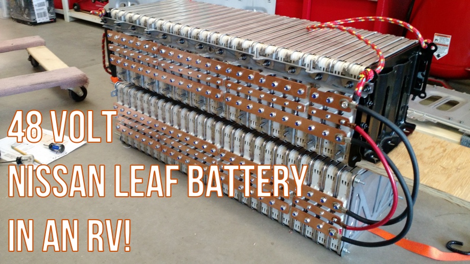
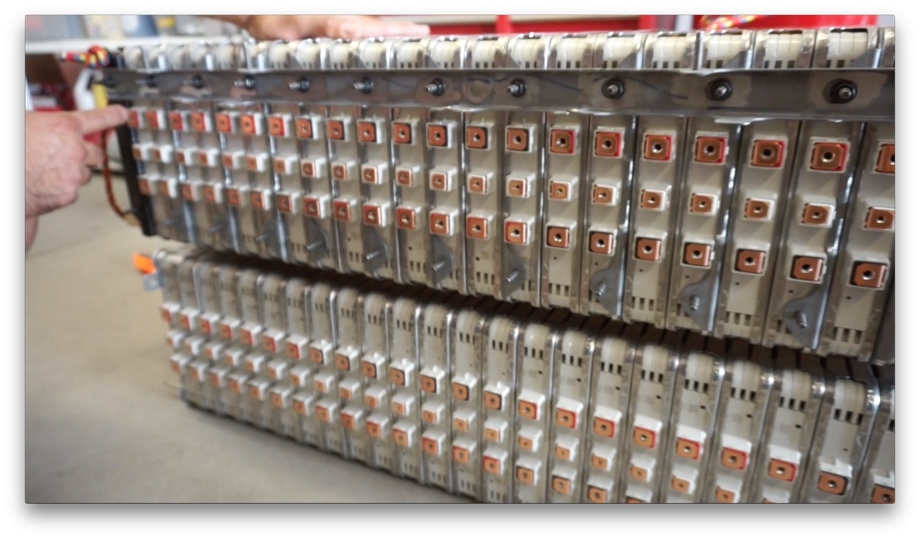
We decided on a layout that had the modules on their sides with the terminals pointing out. With 49 modules in our whole battery, we decided to put 25 on the bottom with 24 on top of those.
The Nissan Leaf modules come in 3 layouts: one with a set of 24 modules lined up on their sides and then two 12 module clusters where they are flat, 4 on one side and 8 on the other.
We really liked the compactness of the layout of the 24 module setup, so we bought long threaded rod at home depot to mimic that layout with the other two clusters. It just so happens that this layout is the exact length of the bay we intend to use.
The first thing we had to do to change the layout was to take the modules off their threaded rods that held them all together. They came from the factory alternating positive and negative on top (all tied in series). We needed seven positive on top, then seven negative on top, then seven positive, etc. We did the same thing with the other clusters, but this time they had 25 modules connected via the rod.
After we repositioned all of them and reconnected them all together on the rods, it was time to connect the terminals. We chose to use 1/8" thick copper bus bar to join our modules together. We went with 1.5-inch width for the main terminals and .75-inch width for the 'sensing' ports in the middles. I would love to say that we chose this based on some calculations we did about the load carrying characteristics of these particular bus bars, but sadly that is not the case. We chose these because they were what we could find on Amazon.com that seemed to fit our needs. That being said, these copper bus bars should flow electricity extremely well and offer very little electrical resistance. It is also much cleaner and easier to work with than trying to use cables to tie all 147 terminals together. Also, it ends up looking pretty amazing.
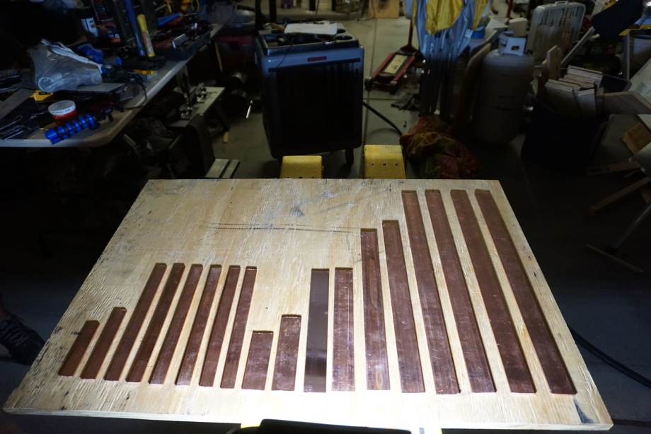
We cut the bus bars to size,
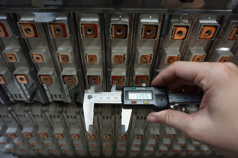
precisely measured the distance between each terminal with calipers (we only had one shot to drill these holes correctly, so we measured down to the thousandth of an inch - it made a big difference),

drilled out 147 holes, and then cleaned them all.

The kids filed, sanded, and polished all of it.
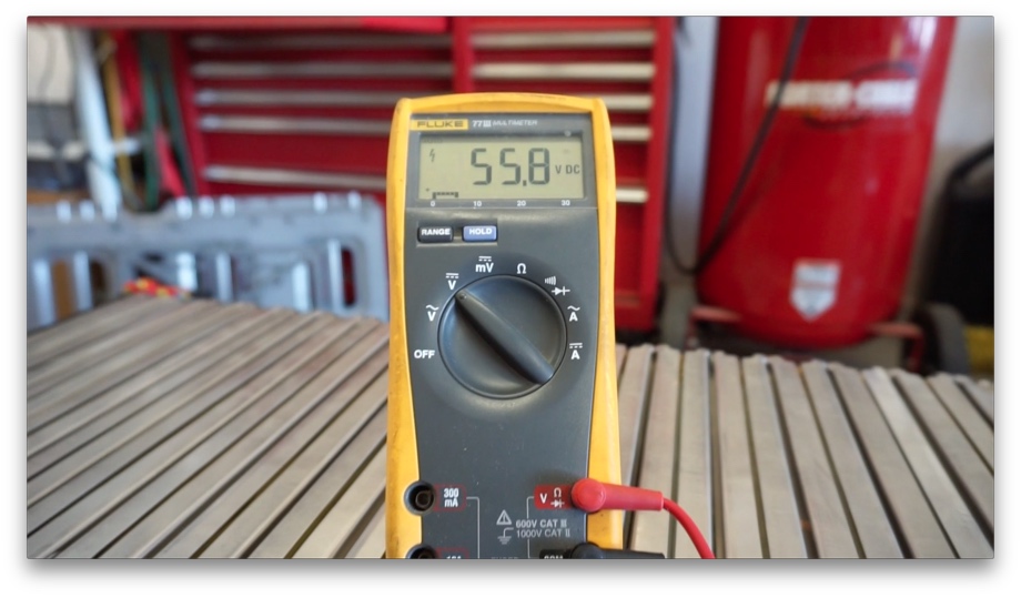
Finally, it came time to put all the bus bars on (and the cables connecting the top and bottom parts of our battery) and see if it actually worked the way we planned.
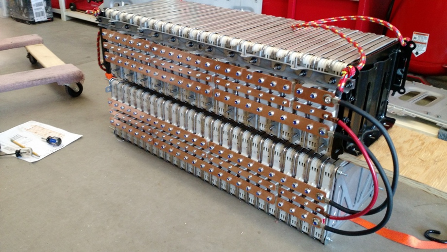
Hallelujah! It works! 55.8V So cool that after coming up with this crazy idea about a year ago and researching for an untold number of hours, the plan actually worked!
Reconfiguring the battery and putting it all together was also a great opportunity for the kids to learn and to help us. They got to learn a little bit about how electricity works - how parallel and series circuits work. How to file, sand, and polish metal. Life skills for the win!
Next up in the battery plan: Building the support system to secure the battery in place in the bay of the bus (don't want it sliding around when we're traveling down the highway)
Parts Used
110 Copper Rectangular Bar 1/8" thick, 1-1/4" Width, 48" Length
110 Copper Rectangular Bar, Unpolished (Mill) Finish, H04 Temper, ASTM B187, 1/8" Thickness, 3/4" Width, 72" Length
Mothers 05101 Mag & Aluminum Polish
Drill America KFD29J-PC KFD 29-Piece High-Speed Steel Jobber Length Drill Bit Set


0 Comments
Comments powered by Disqus